In many industrial plants, engineers notice a strange and frustrating issue: PLC inputs behave perfectly under normal conditions but start flickering, dropping, or turning ON/OFF unexpectedly whenever a motor starts. No logic change, no wiring change; yet the PLC suddenly reports false signals. This problem is often misdiagnosed as a faulty input card or bad PLC program, when in reality the root cause lies in what happens electrically during motor starting.
PLC Inputs Disturbance During Motor Start
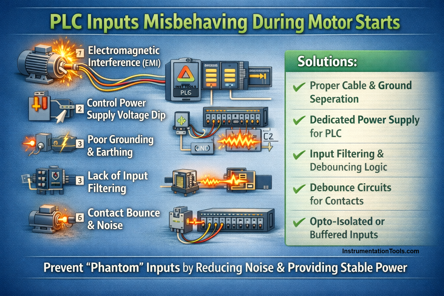
High-rated motors create high inrush currents, electrical noise, and momentary voltage disturbances that can easily interfere with sensitive PLC input circuits if the system is not designed or installed correctly. Understanding this phenomenon is essential because it can lead to nuisance trips, false alarms, and unreliable automation behavior in otherwise healthy systems.
Electromagnetic interference generated during motor starting
When a motor starts, it draws a very high inrush current, often several times its rated running current, which generates strong electromagnetic fields around the motor, its cables, and associated contactors or busbars. These rapidly changing magnetic fields can induce unwanted voltages in nearby conductors, including PLC input wires. If the PLC input cables are routed too close to the motor power lines or are unshielded, these induced voltages can momentarily exceed the input module’s switching threshold.
As a result, the PLC registers false ON or OFF signals, even though the connected sensors or switches have not actually changed state. This issue is particularly noticeable during direct-on-line (DOL) motor starts, star-delta starting, or large variable frequency drive (VFD) operations where the current surge is significant. Proper cable separation, using shielded cables for PLC inputs, and maintaining distance from high-power motor feeders are essential to minimize EMI and ensure reliable input readings.
Control the power supply voltage dip due to the motor start
When a motor starts, the large inrush current it draws can cause a temporary drop in the plant’s electrical supply voltage, including the voltage feeding the PLC and its input modules. This is especially common when the PLC and motor control circuits share the same transformer or distribution panel.
PLC input modules are sensitive to voltage levels, and even a brief dip can cause them to misinterpret steady input signals as OFF or register false ON signals. Unlike EMI, which affects specific input wires, a supply voltage dip can cause multiple unrelated inputs to glitch simultaneously, making it appear as if several field devices failed at the same time.
This problem is more pronounced with older or undersized power supplies and in systems without proper decoupling or voltage stabilization. To prevent this, engineers often use dedicated, well-regulated power supplies for control circuits, add local capacitive buffering, or separate motor power from PLC power, ensuring stable operation even during high-current motor starts.
Poor grounding and earthing are causing reference instability
Proper grounding is critical in any control system because PLC inputs reference their signals to ground. When grounding is inadequate or inconsistent, such as multiple floating grounds, improperly bonded motor frames, or separate earth points, the high currents flowing during motor starting can create ground potential differences across the system.
These differences cause the PLC input modules to see voltages differently from what the field devices actually produce, leading to false ON/OFF readings. Unlike EMI, which affects the signal wires directly, grounding issues can create unpredictable and intermittent problems that are hard to reproduce, often showing up only during motor starts or heavy switching events.
This is why random input glitches appear even though no device has actually changed state. To mitigate this, engineers implement single-point grounding, bond motor frames and panels correctly, and ensure the PLC chassis, I/O modules, and field devices share a common, low-impedance earth reference, providing a stable baseline for all signal measurements.
Lack of software or hardware input filtering
During motor starting, electrical noise often appears as very short-duration voltage spikes on the PLC input lines. These spikes, lasting only a few milliseconds, can be caused by switching contactors, inrush currents, or transient electromagnetic interference. If the PLC input modules have minimal hardware filtering and the PLC program does not implement software debounce or delay logic, the system may interpret these noise spikes as valid input changes.
This results in the PLC registering false ON/OFF events even though the connected sensors or switches remain stable. The problem is particularly noticeable on digital inputs that monitor mechanical contacts, such as limit switches or auxiliary relays, which already have minor inherent bounce.
Hardware solutions include using input modules with built-in filtering, RC filters, or opto-isolated inputs. Software solutions involve introducing short timers or debouncing logic to ignore very brief pulses, ensuring that only sustained, real signals are recognized by the PLC, thus improving system reliability during motor starts.
Inadequate isolation between field devices and PLC inputs
When field devices are directly wired to PLC input modules without proper isolation, the electrical transients generated during motor starting can easily couple into the input circuits. High inrush currents, switching spikes from contactors, or electromagnetic interference can transfer through the wiring, causing the PLC to register false ON or OFF signals even though the connected devices remain stable.
This problem is particularly pronounced in systems where the PLC inputs are not opto-isolated or electrically buffered, or where long unshielded cables run near high-power motor feeders. Without isolation, the PLC essentially sees all the noise as legitimate input activity, leading to chattering, unexpected trips, or incorrect logic execution.
To prevent this, engineers typically use opto-isolated input modules, interposing relays, or signal conditioners between the field device and the PLC. These measures block transient currents and voltage spikes, ensuring that only the intended field signal reaches the PLC, thereby maintaining reliable input operation even during heavy motor starts or other switching events.