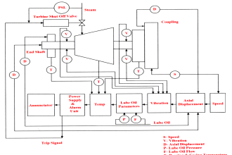
In industrial automation, it is very common to see PLC logic perform flawlessly in simulation but behave unexpectedly once deployed in the actual plant. This happens because a simulation environment represents an ideal and controlled version of the system, while the real field environment is dynamic, asynchronous, and affected by physical, electrical, and human factors.
PLC Logic Works on Simulation but Fails in Field
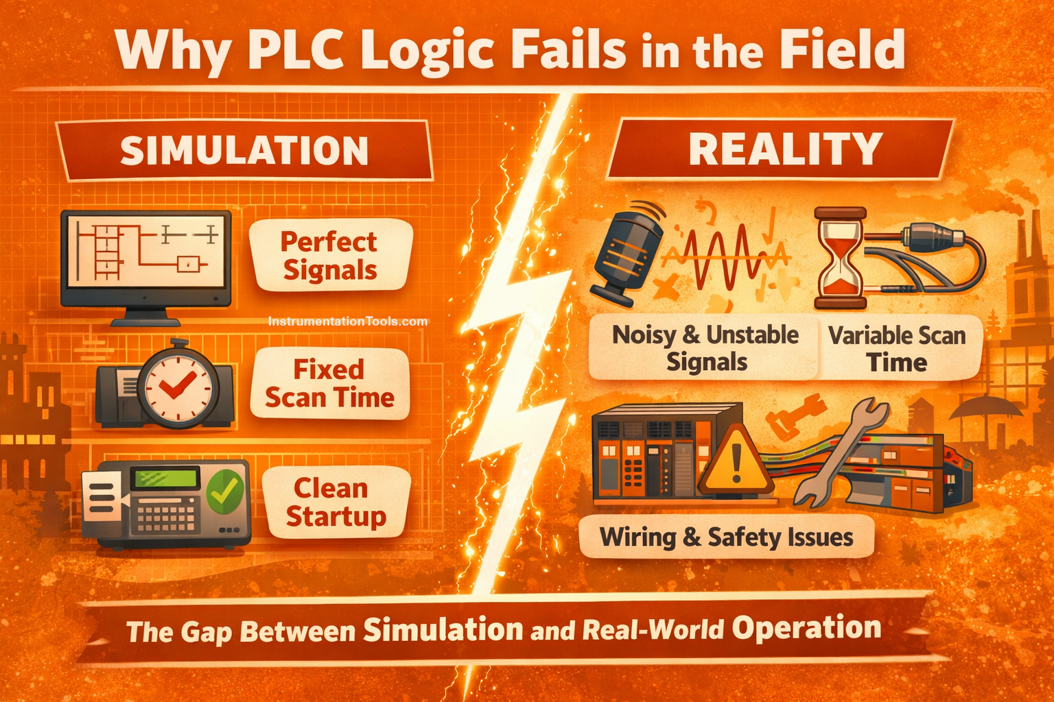
Simulators validate the functional flow of logic, but they cannot fully replicate real-world signal behavior, communication delays, hardware response times, power-up conditions, or operator interactions.
As a result, logic that appears correct during offline testing may fail, misfire, or become unstable during commissioning or operation in the field. Understanding this gap between simulation and reality is essential for designing PLC programs that are robust, fault-tolerant, and truly plant-ready, which will be seen in this post.
Simulation uses an ideal perfect value as input
In a PLC simulation, input signals behave in an ideal and unrealistic manner. When an input is turned ON in simulation, it changes cleanly from 0 to 1 in a single scan, remains stable, and never fluctuates unless the engineer deliberately forces it. There is no electrical noise, no mechanical vibration, no contact bounce, and no process variation. Because of this, the PLC logic always receives a perfect signal, exactly matching the conditions expected by the program.
In the real field, inputs come from physical devices such as proximity sensors, limit switches, pressure switches, and transmitters. These devices are influenced by mechanical movement, wear, vibration, temperature, electrical interference, and alignment. A digital input may briefly turn ON and OFF multiple times within a few milliseconds due to contact bounce or noise. An analog signal may hover around a threshold value and continuously fluctuate instead of crossing it cleanly. As a result, the PLC may never see the stable transition that the logic expects.
When PLC logic is written assuming clean transitions, such as using rising-edge detection, one-shot instructions, or direct comparisons without filtering, the logic works in simulation but fails in the field. The edge may occur too fast, multiple times, or not at all from the PLC’s perspective. This leads to missed triggers, multiple unintended triggers, or logic that appears to randomly fail during actual operation, even though it worked every time in simulation.
Scan time behaviour is unrealistic in the simulation
In a PLC simulation environment, the program usually runs with a stable and predictable scan time. The simulator executes logic quickly, without real communication load, without heavy diagnostics, and without background tasks competing for CPU time. Because of this, the sequence of logic execution appears smooth and deterministic; each rung seems to execute immediately after the previous one, exactly as the programmer expects.
In the real field, PLC scan time is never constant. It varies continuously based on factors such as HMI communication, network traffic, remote I/O updates, drive communication, data logging, alarms, and diagnostics. During peak load, the scan time can increase significantly. When this happens, timers may expire later than expected, sequential logic may overlap, and assumptions about execution order break down.
Logic that depends on precise timing, such as expecting a timer to complete within a narrow window, or assuming that a status bit will be evaluated in the very next scan, can therefore work in simulation but fail in real operation. This often results in sequences that hang, steps that skip, or interlocks that trigger unexpectedly, even though the logic itself is functionally correct.
Real I/O and network latency are ignored in simulation
In simulation, input and output signals appear to update instantly. When the PLC sets an output, the corresponding feedback is often forced immediately or assumed to be true in the same scan. There is no delay between command and response, and no uncertainty about when a signal will arrive. This creates the illusion that field devices react immediately to PLC commands.
In real systems, most I/O is not local and instantaneous. Remote I/O racks, Ethernet-based fieldbuses, VFDs, servo drives, and intelligent instruments all introduce communication delays. Data is exchanged based on RPI (Requested Packet Interval), device processing time, and network conditions. Feedback signals often arrive one or more scans after the command is issued, and sometimes even later during network congestion or startup.
If PLC logic advances to the next step without explicitly waiting for confirmed feedback, the program may move faster than the physical system. This results in premature step transitions, false fault detection, or sequences that appear unstable. These timing-related issues do not appear in simulation because the simulator does not model real communication latency, making the logic seem reliable until it is tested in the field.
Power-up and restart conditions are not realistic
In simulation, the PLC program usually starts in a clean and predictable state. All internal bits, timers, and sequences are initialized neatly, and simulated field devices appear ready immediately. There is no concept of machines being mid-cycle, valves partially open, or drives still booting. This creates a best-case startup scenario that rarely exists in real plants.
In the field, PLC restarts often occur during abnormal or partially completed operations, after a power failure, emergency stop, or maintenance activity. Field devices may retain their last physical position, sensors may power up slower than the PLC, and communication with remote I/O or drives may take several seconds to establish.
During this time, the PLC logic may evaluate incomplete or invalid feedback. If the program does not explicitly handle startup and recovery conditions, it may interpret these temporary states as faults or unsafe conditions. Interlocks may trigger immediately after power-up, sequences may refuse to start, or equipment may behave unpredictably. These problems never appear in simulation because the simulator does not represent real-world restart behavior or device warm-up delays.
Race conditions are hidden in the simulation
In simulation, engineers usually force inputs and internal bits manually and sequentially; one signal is changed, the result is observed, and then the next signal is modified. This controlled interaction hides timing conflicts and gives the impression that the logic is stable. Only one condition appears to change at a time.
In the real field, multiple signals can change within the same PLC scan. For example, a command bit from the HMI, a feedback signal from a device, and an interlock status may all change simultaneously. When logic is not carefully structured, this can create race conditions where two rungs attempt to set or reset the same output in the same scan, or where a command is both accepted and cancelled instantly.
These situations lead to intermittent and confusing behavior where outputs flicker, sequences jump steps, or commands appear to be ignored. Because simulation does not naturally expose simultaneous signal changes, race conditions often remain hidden until commissioning, making the logic seem unreliable only in the real plant.
HMI interaction is oversimplified in the simulation
In a simulation setup, HMI interaction is usually very controlled. There is typically one user, one screen, and deliberate button presses made one at a time. Buttons are pressed briefly, commands are issued once, and mode changes happen in an orderly way. Under these conditions, PLC logic responds exactly as expected.
In real plant operation, multiple operators may interact with the system from different HMIs at the same time. Buttons may be pressed repeatedly, held down for several seconds, or pressed again before the previous command has completed. Operators may also navigate between screens quickly or issue conflicting commands unintentionally.
If the PLC logic does not include proper handshaking, command latching, and validation, these real-world interactions can cause commands to retrigger, states to be overwritten, or modes to change mid-operation. These issues are rarely seen in simulation because the simulator does not reproduce real operator behavior or concurrent HMI access.