In industrial automation systems, it is always necessary to program the system by reading all the documents first. It has a wide variety of documents, and a programmer thus needs to understand the differences and applications. If he is clear with each of their meanings, then only he can implement them properly in his projects. One such document is a control logic chart or CLC. In this post, we will see what a control logic chart is in automation systems.
What is a control logic chart?
As the name implies, a control logic chart is a document that defines how the logic will be executed in a controlled manner. All programmers know that they require a document to refer to how the logic will be executed. The most general document that we refer to is a control philosophy for this purpose.
A control philosophy refers to the overall automation document, which covers the overall process and its groups, modes of operation, operation sequence overview, safety concept, overview of interlocks, operator interactions, alarms and events philosophy, system architecture reference, and basic rules to automate the plant. But all this is only an overview, which gives the first impression of the automated plant.
Yes, it will help to create logic, but not in detail. If you are a very expert programmer, then only you can make the program yourself properly by reading the control philosophy. So this issue is overcome by a document called the control logic chart.
A CLC is a document that gives in detail all the information, like instrument alarms and their corresponding actions on the process, the meaning of each setpoint that will be entered from SCADA or HMI, decisions, and transitions in a clear format. Also, if the logic sequence is small, then that too is covered here. Otherwise, another document called an operating sequence chart is used, which describes the logic sequence in detailed steps.
A control logic chart contains the following things:
- Inputs and conditions
- Decisions or logic states
- Steps or actions
- Sequences
- Interlocks and safety logic
So when a control logic chart is prepared, it generally has the following table entries:
- Tagname
- Type
- Description
- Equipment
- Component
- Setpoint
- Range Min
- Range Max
- Units
- Set
- Action ot derivation
- Reset
Let us understand this by an example. Refer to the image below for more details. As you can see, we have a raw water tank which has the following components: four motors and a level transmitter. So, to automate this tank in detail and with proper interlocks, we develop a control logic chart.
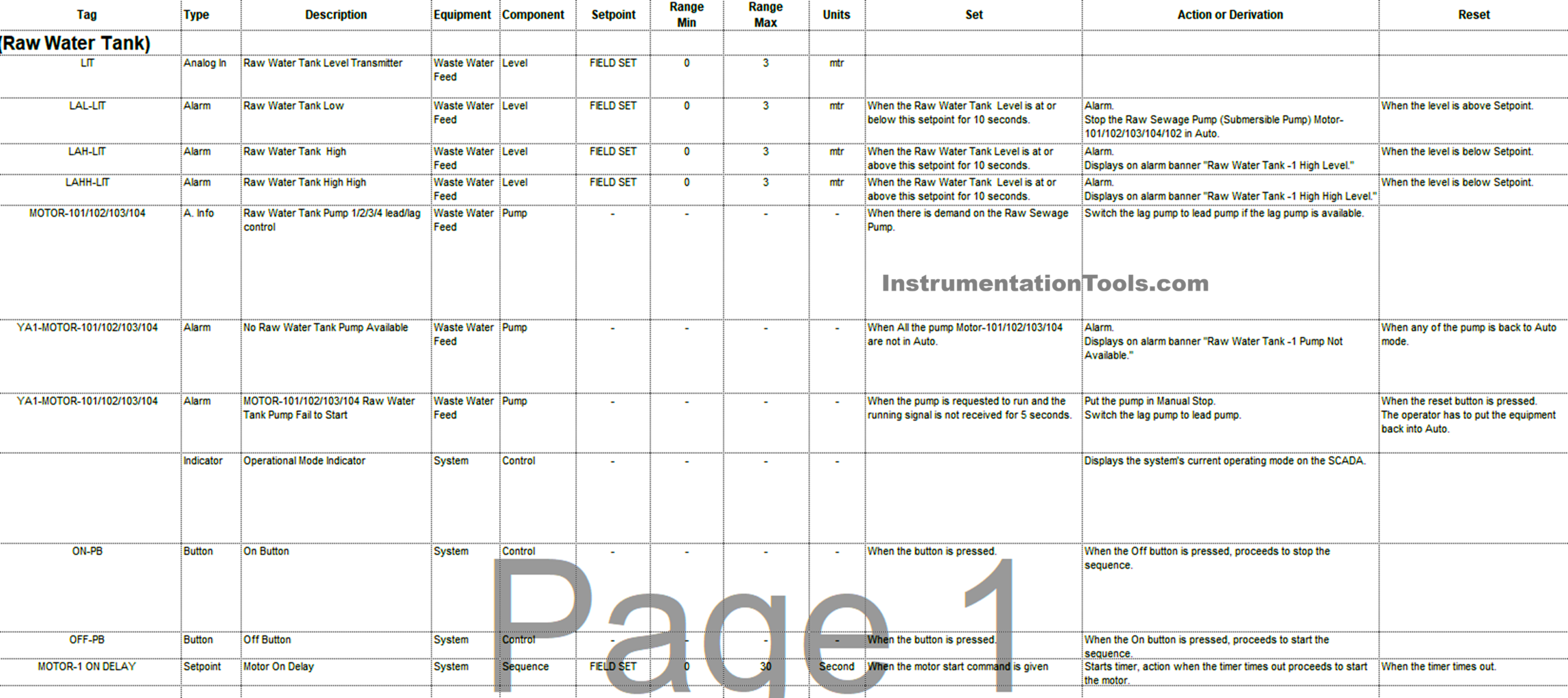
We first start with the level transmitter. It indicates the location of the instrument and its scaling range. Then, for this instrument, we generate alarms. Each alarm will have a description that needs to be shown in SCADA. The set point for these alarms will have a minimum and maximum range that needs to be entered in SCADA. Then, we need to write how the alarm occurs and what happens when that alarm comes. Also, we need to describe how the alarm is reset.
Similarly, we write the logic chart for the motor, describing its alarms and operations. Then we describe what all operator buttons and setpoints are required for this tank in the SCADA to be operated in auto or manual mode. In short, you must have seen that we covered the inputs and conditions, decisions, steps, and interlocks very simply and in an understandable manner in the chart. If the motor had a complex sequence of operation, then that would have been covered in the operation sequence chart.
So when you compare control logic charts with control philosophy, you will find that the control logic chart has defined the exact PLC logic, very detailed level programming, exact interlocks and sequences, exact alarm triggering conditions and their actions, and then can be readily implemented by the programmer to develop and use at the site. All this information would not have been possible in a control philosophy, as it already covers the whole plant overview.
That is why a control logic chart is very important to be developed and implemented, because the control philosophy will only say what to do, but the control logic chart will say how to do it.