Inst ToolsInst ToolsInst Tools
  • Courses
  • Automation
    • PLC
    • Control System
    • Safety System
    • Communication
    • Fire & Gas System
  • Instrumentation
    • Design
    • Pressure
    • Temperature
    • Flow
    • Level
    • Vibration
    • Analyzer
    • Control Valve
    • Switch
    • Calibration
    • Erection & Commissioning
  • Interview
    • Instrumentation
    • Electrical
    • Electronics
    • Practical
  • Q&A
    • Instrumentation
    • Control System
    • Electrical
    • Electronics
    • Analog Electronics
    • Digital Electronics
    • Power Electronics
    • Microprocessor
  • Request
Search
  • Books
  • Software
  • Projects
  • Process
  • Tools
  • Basics
  • Formula
  • Power Plant
  • Root Cause Analysis
  • Electrical Basics
  • Animation
  • Standards
  • 4-20 mA Course
  • Siemens PLC Course
Reading: Learn about SCADA and HMI Systems
Share
Notification Show More
Font ResizerAa
Inst ToolsInst Tools
Font ResizerAa
  • Courses
  • Design
  • PLC
  • Interview
  • Control System
Search
  • Courses
  • Automation
    • PLC
    • Control System
    • Safety System
    • Communication
    • Fire & Gas System
  • Instrumentation
    • Design
    • Pressure
    • Temperature
    • Flow
    • Level
    • Vibration
    • Analyzer
    • Control Valve
    • Switch
    • Calibration
    • Erection & Commissioning
  • Interview
    • Instrumentation
    • Electrical
    • Electronics
    • Practical
  • Q&A
    • Instrumentation
    • Control System
    • Electrical
    • Electronics
    • Analog Electronics
    • Digital Electronics
    • Power Electronics
    • Microprocessor
  • Request
Follow US
All rights reserved. Reproduction in whole or in part without written permission is prohibited.
Inst Tools > Blog > Control Systems > Learn about SCADA and HMI Systems

Learn about SCADA and HMI Systems

In this article, we will learn about the SCADA and HMI systems in industrial automation, also the differences and comparisons.

Last updated: September 28, 2022 4:12 pm
Viral Nagda
Control Systems PLC Tutorials
1 Comment
Share
5 Min Read
SHARE

In this article, we will learn about the SCADA and HMI systems in industrial automation, also the differences and comparisons.

Contents
HMISCADA

The graphical interface is a must in industrial automation to view the graphics and control actions happening inside a PLC or other controller. The two commonly used graphical interfaces are HMI and SCADA.

HMI stands for Human Machine Interface, and SCADA stands for Supervisory Control and Data Acquisition. Both have the same task of graphical display, but stand out from each other in some differences. In this post, we will see the difference between HMI and SCADA.

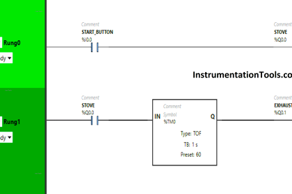
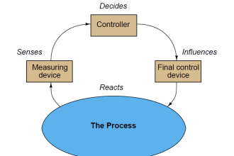
Let us first understand the flow of system control. Consider we are using a button, motor, PLC, and HMI / SCADA. A button is a digital input for PLC and a motor is a digital output for PLC.

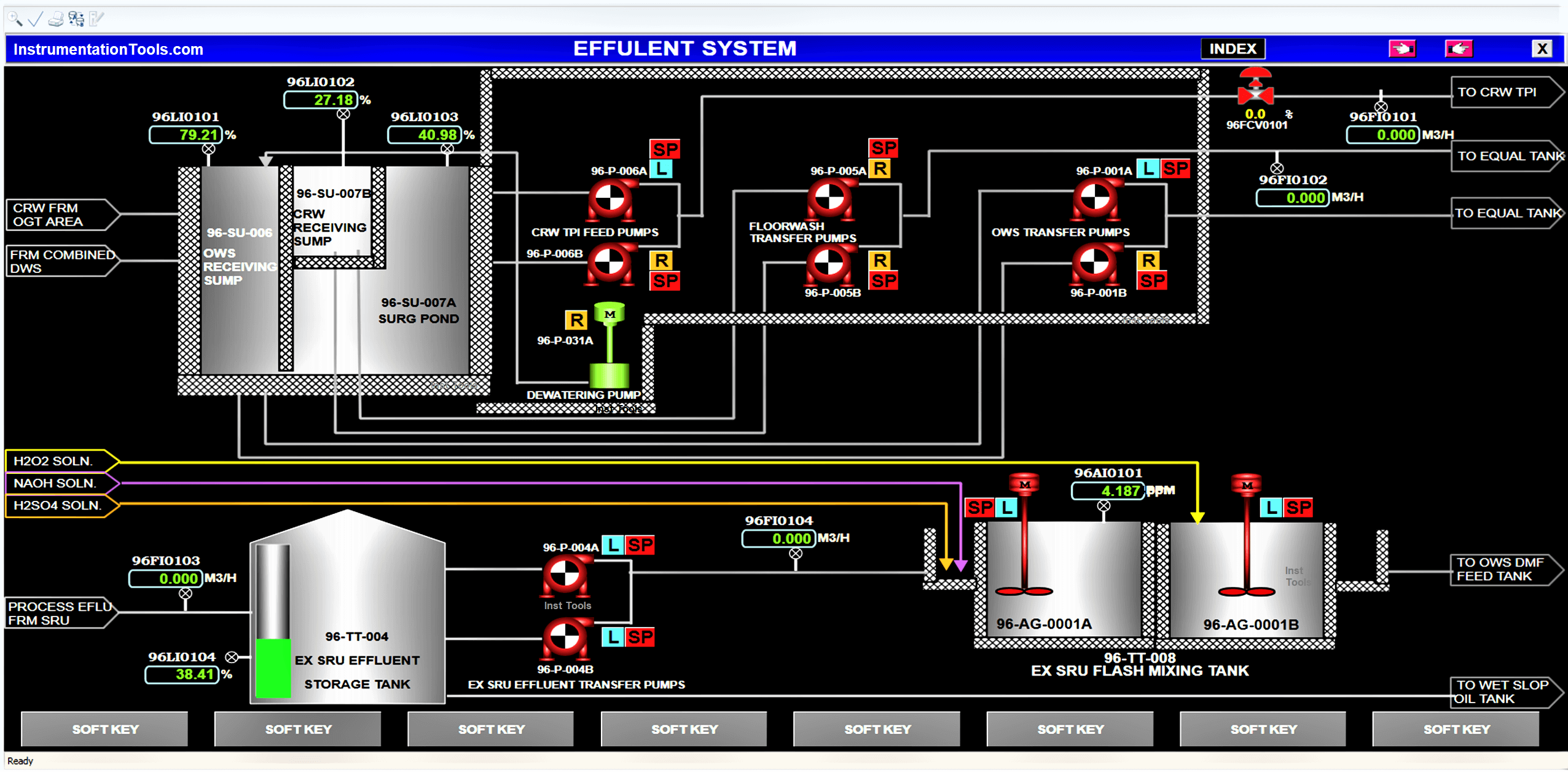
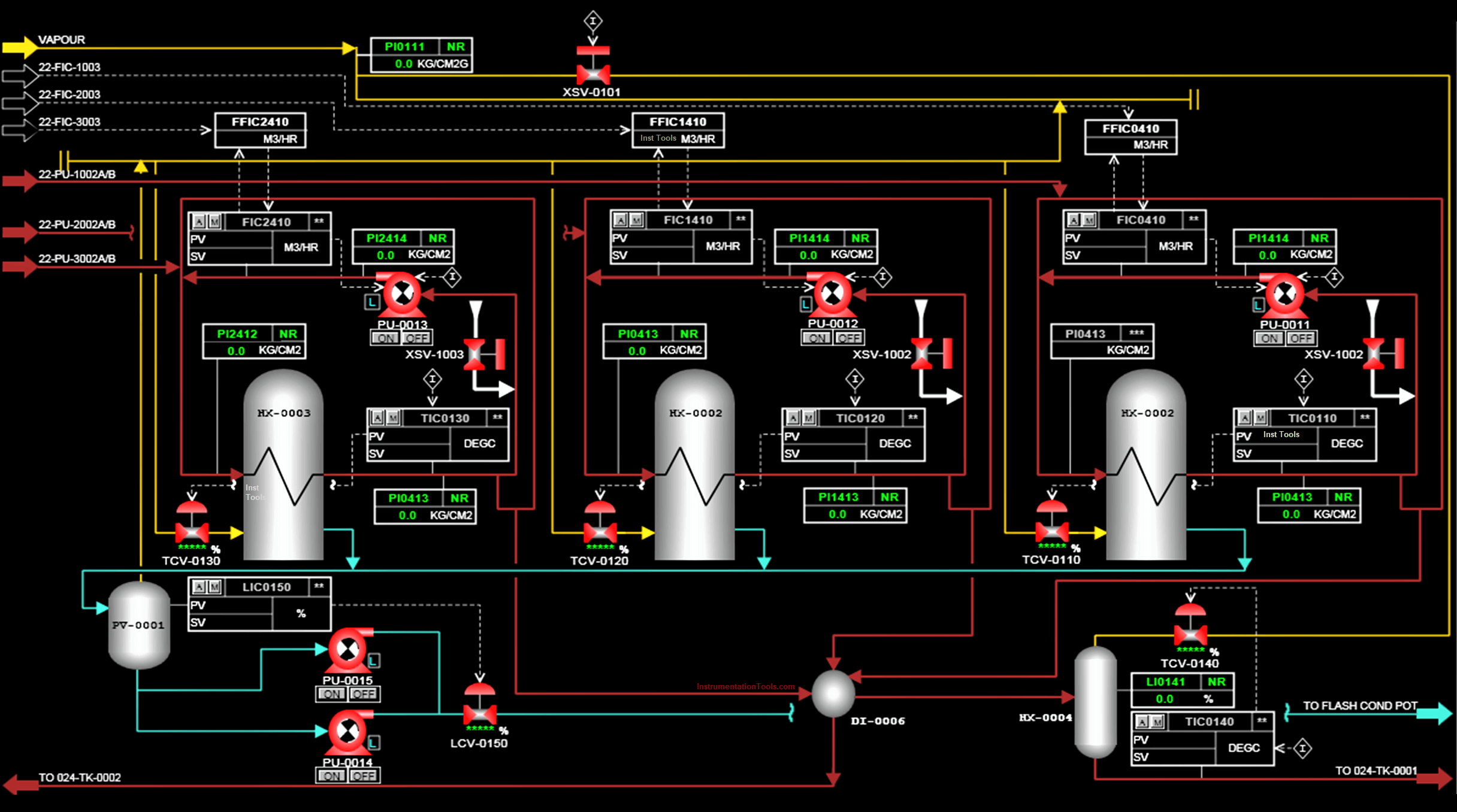
In the HMI / SCADA screen, you are showing the status of the motor. It is communicating with PLC and shows the status through it.

On pressing the button, the logic written in PLC turns on the motor. So, the motor status will turn from red to green on the display screen.
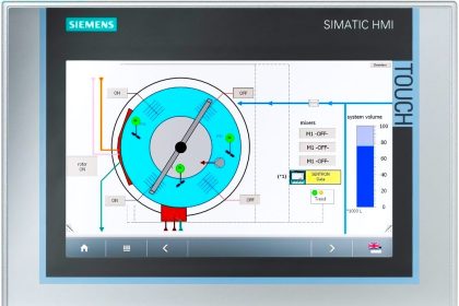
HMI

Basically, HMI or SCADA is just like the regular monitor that we use. It has no brain; it just shows all the processes happening inside the CPU.

SCADA HMI

In the same way, it needs to communicate with PLC for showing and data.

To control data, if we consider the previous example; instead of a hardwired push button, you can show a button on the display and make it editable for the user. The user will press the button on the display and can eventually start the motor.

Free SCADA Training Courses:

  • InTouch SCADA Course
  • WinCC SCADA Course

Let us see the differences between both of them. First of all, SCADA is software that needs to be installed in a PC for working; whereas HMI is an individual device itself which just needs to be powered up.

As it is an individual device, it needs a separate SMPS wherever it is installed; whereas a PC can normally be powered up as we use it in daily life.

SCADA Tutorial 1 -  What is SCADA? | Online Free SCADA Course

Suppose there are 10 processes in a plant. In that case, 10 HMI’s will be required for the individual processes. Obviously, a single HMI can also control all the 10 processes.

But, HMI has some limitations in communication. It will not completely slow down the communication of 10 PLC’s in a big way and show data in a lagging way; but yes, as more controllers are added to the single HMI, a bit of communication lag will happen in the HMI and the data will be shown a little slower in it.

SCADA

For this purpose, SCADA is used. SCADA is purposely designed for such cases where you have to show all the processes of the plant on a single screen. Communication is way faster in it and it will show all the data smoothly.

HMI

HMI is cheaper than SCADA. If you have only two processes, it makes sense to connect a single HMI for 2 PLC’s; instead of using a SCADA.

HMI and SCADA are even both used in tandem in many cases. In our previous example of 10 processes, it makes sense to connect 10 HMI’s for individual stations so that the local operator can understand them easily. And, connect a SCADA in the central control room for an engineer to monitor the whole plant.

In terms of features, SCADA is a bit higher in functions like server-client, audit trail, reporting, web server, trends, database, etc.

Mostly, HMI has all this too apart from the server-client function. But, even in the available functions, it has some limitations as compared to that available in SCADA. It is because SCADA is designed for handling large-scale processes and this requires it to be at a higher level every time for properly controlling the plant. 

In this way, we understood some general differences between HMI and SCADA.

If you liked this article, then please subscribe to our YouTube Channel for Instrumentation, Electrical, PLC, and SCADA video tutorials.

You can also follow us on Facebook and Twitter to receive daily updates.

Read Next:

  • Data Types in PLC
  • Types of PLC Memory
  • Commissioning of DCS System
  • What is Hot Standby in PLC?
  • Sequential Function Chart
Don't Miss Our Updates
Be the first to get exclusive content straight to your email.
We promise not to spam you. You can unsubscribe at any time.
Invalid email address
You've successfully subscribed !

Continue Reading

PLC Ladder Logic for Sensor Scaling with Offset
Troubleshooting PLC Permissive Inputs
How to use JUMP Instruction in PLC Ladder Logic?
History of Internet of Things (IOT)
Difference Between Industrial Computer (IPC) and Normal Computer (PC)
Define the Order of Execution in Functional Block Diagram of Studio 5000
Share This Article
Facebook Whatsapp Whatsapp LinkedIn Copy Link
Share
1 Comment
  • Munmun Singh says:
    December 18, 2023 at 1:54 pm

    Hi,

    How we calculate optical fibre cable losses.

    Reply

Leave a Reply Cancel reply

Your email address will not be published. Required fields are marked *

Stay Connected

128.3kFollowersLike
69.1kFollowersFollow
210kSubscribersSubscribe
38kFollowersFollow

Categories

Explore More

PLC Sequence Programming Ladder Logic
Omron PLC Online Training Course
What is Sequential Function Chart (SFC?)
Derivative Controller Principle
PLC Memory Mapping and I/O addressing
How to Implement Ratio Control in this System?
Difference between Router, Switch, and Hub
Machine Tool and Coolant Control: PLC Ladder Logic Design

Keep Learning

PLC Motor Control Circuit-3

Basics of PLC Programming

PID block from the PLC library

How to Configure PID Controller in Various Schneider PLCs?

Control Valve Split Range Example - 2

Control Valve Split Range Example

de-energized-to-safe-mode

De-energize to Safe Loop philosophy

What is the consumed tag in Studio 5000 software?

Produced Tags and Consumed Tags in Studio 5000

PLC to PLC Communication using S7 Connection

PLC to PLC Communication using S7 Connection PUT & GET Instructions

Light ON OFF Control using PLC

Light ON OFF Control using PLC

Car Wash Program using Functional Block Diagram (PLC)

Car Wash Program using Functional Block Diagram (PLC)

Learn More

Simulator in S7-1200 and S7-1500 PLC

How to Work With Simulator in S7-1200 and S7-1500 PLC?

Single Push button to ON and OFF a Bulb using Ladder Logic

Single Push button to ON and OFF a Bulb using Ladder Logic

Ladder Rung with Two Outputs

PLC Multiple Outputs Configuration

Ash Handling System in Thermal Power Plant

Ash Handling System in Thermal Power Plant

Address Overlapping in Tia Portal

How to Check Address Overlapping in Tia Portal?

OTDR testing

OTDR Testing

Fieldbus Flow Transmitter Configuration

Fieldbus Flow Transmitter Configuration

Ideal Diode Characteristics Curve

Difference between ideal diode & conventional diode

Menu

  • About
  • Privacy Policy
  • Copyright

Quick Links

  • Learn PLC
  • Helping Hand
  • Part Time Job

YouTube Subscribe

Follow US
All rights reserved. Reproduction in whole or in part without written permission is prohibited.
Welcome Back!

Sign in to your account

Username or Email Address
Password

Lost your password?