Selecting the right valve for the process control requires that the engineer should be able to:
- Ensure that the process requirements are properly defined. The process of collecting data for sizing such as Pressure, flow rates, vapor pressure, densities, temperature, and viscosities.
- The requirement that the valve must live up to during startup, shutdown and emergency conditions
- To select the right control valve, one must understand normal operating conditions also.
- Calculate the required flow capacity over the operating range of the control valve.
- Determine any unfavorable conditions such as cavitation and noise and know how to deal with them.
- Know how to select the valve that will satisfy the limitations of price and maintainability while providing good performance in the control of the process.
What is Valve Sizing?
Valve sizing is a procedure with a set of specified process conditions that ensures the correct valve capacity.

Purpose of Control valve sizing
The first step in finding the size of a valve is to calculate the flow coefficient (Cv) which is important for the system.
The process of “control valve sizing” is a procedure where the process dynamics of the system are matched to the performance characteristics of the valve. This produces a control valve of an appropriate size and type that will best meet the needs of managing flow within the processing system.
Every attempt should be made to carefully and accurately to size and select a control valve for the required application.
Why is control valve sizing so important?
An undersized control valve can’t pass the required flow through it. But, actually, in several instances, a control valve is too large for the application.
An oversized valve is very sensitive to process operating conditions. Even the smallest changes in valve position will cause significant changes in inflow. This makes it difficult or even impossible for the valve to the exact tune of the required flow. A highly oversized valve will operate in an almost closed state, which is unstable and undesirable.
Also Read:
Selecting a properly sized control valve is required to reach the highest degree of process control for the liquid, gas, or multi-phase fluid”.
For best process control applications:
- Size the control valve to operate 20% to 80% open at the maximum required flow, and not less than 20% open at the minimum required flow.
- Properly sized full ball valve, segment ball valve, and high-performance butterfly valves are most often two sizes smaller than that of the process line.
- Properly sized globe valves are usually one size smaller than the process line.
- The trim characteristic is selected to produce a good performance; the Main objectives are usually linear control loop behavior along with acceptable rangeability.
- The valve body can be selected based on the features and the as usual availability. Note that the valve size is either equal to the pipeline size or slightly less. To make process piping connections an inlet reducer and outlet expander are required when the control valve size is smaller than the process piping.
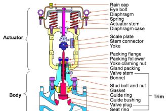
Actuator Power:
The actuator is sized based on the thrust that is required to overcome the unbalanced forces in the valve body and seating force. Also based on stiffness necessary for stability.
Actuator Speed of response:
Actuator speeds can be increased by enlarging the airflow ports and by installing booster relays. On/off valves, the addition of a quick dump exhaust valve will fast increase the venting rate.
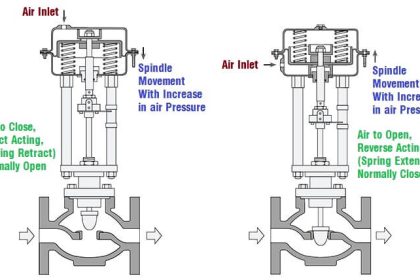
Valve Failure Position:
It is the responsibility of the process control engineer to specify the valve failure position. It is a general practice to fail the energy supply valve (steam, hot oil, and so on) closed. Energy removing valves (cool or chiller water ) open.
The flowsheet abbreviations can be
FC – fail closed
FL – fail in the last position
FI – fail indeterminate (not exactly known)
FO – fail-open
Importance of the Positioner:
Actuator without springs always requires a positioner.
The positioner will increase the actuator thrust by increasing the pressure or volume.
Changes in packing friction due to dirt, corrosion, lack of lubrication, the variation of dynamic forces of the process can be overcome with the addition of a positioner.
Also Read:
- Control Valve Positioner Principle
- Functional Testing of Positioner
- Electro-Pneumatic Valve Positioner
Actuator Selection
The spring-and-diaphragm actuator is a low cost, provide high thrust at low air supply pressure.
Linear piston actuators do provide longer strokes and can operate at higher air pressures
Rotary piston actuators do operate at higher air pressures and can provide higher torque, suitable for throttling large ball or butterfly valves.
Read Next:
- Basics of Valve Actuators
- Types of Control Valve Actuators
- The relation between Cv and Kv
- Types of Failures in Valves
- Control Valve Stroke Test