Measurement principle
The nucleonic measuring principle is based on the attenuation of gamma radiation as it penetrates materials. The radioactive isotope (gamma source) is installed in a container, also referred to as shielding, which emits the radiation only in one direction.
The source container and the transmitter detecting the radiation are usually mounted on opposite sides of a vessel or pipe.
The emitted radiation (e.g. gamma rays) passes through the vessel walls and the medium contained in the vessel.
The actual measuring effect results from the absorption of the radiation by the medium.
The intelligent transmitter calculates the level, density or the concentration of the medium from the radiation received.
The higher the level or the density of the medium in the vessel the lower the intensity of the radiation received.
In conventional level and density measurements 137 Cesium and 60 Cobalt are commonly used. 241 Americium or 244 Curium may be used for heavy element measurement in a medium consisting of lighter elements.
Continuous level measurement/full absorption
In this measurement principle, the radiation is fully absorbed. The radiation difference between the source and the detector varies given the image of the level. The radiation activity is calculated from the pulse rate received.
Typically the pulse rate (radiation level) at 100% level is zero, meaning the gamma rays are completely absorbed by the medium (full absorption). For example, at 50% of the full range level, only the upper part of the detector receives the radiation. Consequently the pulse rate increases.
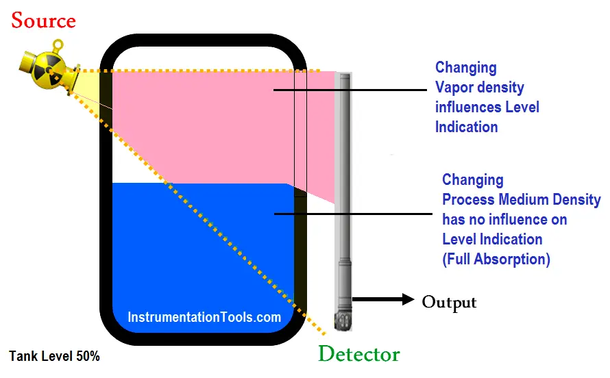
Figure – Changing Process Medium Density has no influence on Level Indication (Full Absorption)
Interface measurement
In nucleonic interface measurement, the source may be inserted in an enclosed dip tube with a cable extension which excludes any contact of the source with the medium.
Depending on the measuring range and the application, one or several detectors are mounted on the outside of the vessel.
The intelligent transmitter measures the average density of the medium between the source and the detector from the radiation received.
A direct relationship to the interface layer can then be derived from this density value.
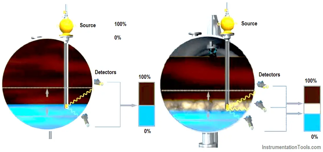
Figure – Nucleonic Interface Measurement Principle
Density profile
The most exact information on the oil/water emulsion layer is achieved by a multi‐detector solution, the so‐ called profiling.
Several transmitters are arranged on the vessel on a vessel wall or inside the vessel.
Each detector measures an absorption image of the density.
The measuring range is subdivided into zones and an applicable density value is calculated for each zone.
The density image is analyzed via an algorithm and visually provided on a monitor.
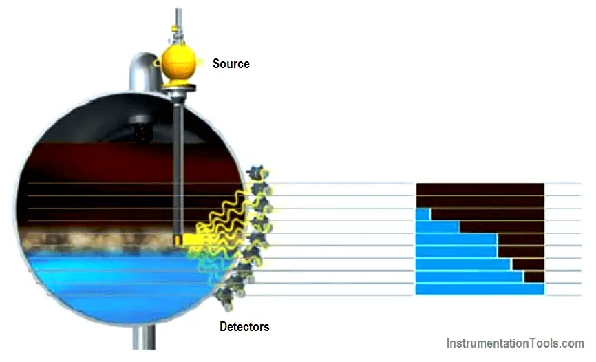
Figure – Nucleonic density profile principle
Limitations
In many countries, the use of nucleonic systems requires the possession of a license due to the potential hazard to personnel. In order to be in accordance with local, state, and federal regulations extensive paper work might be required. The installation is regulated at the local, state, and on the federal level. Sometimes a periodic wipe testing has to be conducted.
Government regulations may require the appointment of a radiation safety officer responsible for enforcing regulations at the owner’s site, including periodic inspections and tests of all nuclear gauges.
Depending on instrument design some applications may require extremely large sources, which can increase delivery times, licensing requirements, and may require special mounting consideration.
Sensitivity to X‐ray (NDT (non‐destructive testing) methods) can cause a false trip to a running unit.
Nuclear devices can be difficult to calibrate accurately. It may be required to empty and fill the vessel to zero and span the device to obtain the desired calibration accuracy. The hard part is normally related to how practical/easy it is to get the required process conditions for calibration.
Due to the fact that the source containers use lead to shield the radiation, the containers can be very heavy and a crane might be required for installation.
The use of nucleonic measurement principles for fast control loop or safety application should be evaluated based on required response time (as the profile is reconstructed from density profile using several sources/detectors and calculation units).
Depending on distance and position of source to sensor, small levels of foam can have significant effect on the measurements. This is due to the density difference between foam end gas vapours.
Interface measurement/density profile may be used if the emulsion layer thickness or the density profile needs to be measured. However If specific values ρwater and ρoil of an emulsion have been used during the calibration stage, then the operated values of ρwater and ρoil should be the same otherwise it will not be possible to characterize the other layers.
For example that if the oil density varies from 900 kg/m (calibration value) to 800 kg/m 3 and if 800 kg/m 3 have been ‘declared’ as ‘emulsion’ then the new oil density will be seen as an emulsion.
Selection
Nucleonic level measurement is used in situations where other instruments cannot be placed in a vessel or reactor due to very corrosive or extremely adhesive products, in reactors or furnaces at very high pressures and/or temperatures.
Design
A nucleonic system needs to be engineered according to the application requirements. The source activity required is calculated based on the vessel design (wall thickness, wall material, etc.) as well as the installation possibilities.
Additional aspects to be considered are: measuring range, the density of the process medium, expected thickness and density of build‐up formation (if any), obstacles in vessel and the ambient temperature at the detector.
In terms of an interface measurement or density profile system engineering is required to determine the correct position of the nuclear source. If the source needs to be placed inside a dip tube, an appropriate nozzle needs to be available. The dip tube can be curved if required to allow the source to be inserted to the correct point even if no suitable spare process connection is available.
For interface or profiler applications, if the measurement range exceeds 1.5 m more than one source is required.
Proper shielding needs to be considered, depending on the expected dose rates (empty vessel).
Particular attention should be paid to the temperature of the detectors. Typically detectors can operate in ‘standard’ process conditions. Therefore, for some applications, a cooling system may be required. If it is the case the cooling systems should be included in the design and submitted to the product manufacturer for approval. This cooling system should minimum comprise header from the cooling skid, suitable tapping point with isolation valves between header and detectors, a water cooling skid (centrifugal pump, air cooler, expansion bottle, temperature and pressure gauges as required, temperature, pressure and flow transmitters as required).
Installation
This level measurement may have the source(s) and the detector(s) internally or externally mounted (see below Figures)
This mounting arrangement should be studied taking into account fluids, process connections, vessel material, the source and detector distance and angles between the source and the detector. This study should highlight the mounting arrangement pro and cons.
Equipment mounted externally or internally might require additional supporting structures.
The applicable sketch should be developed based on the vessel shape and material, the fluid features (including build‐up), the operation and maintenance requirements (e.g. on site calibration). The sizes and distances stated in the here under should be studied.
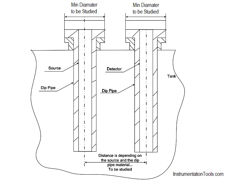
Figure – Nucleonic internal source and detector principle in two separated dip pipes example
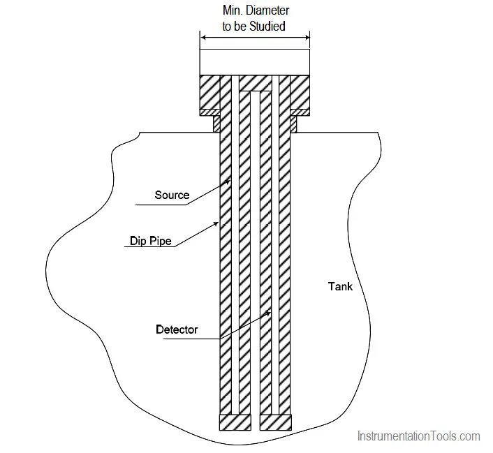
Figure – Nucleonic internal source and detector principle in one dip pipe example
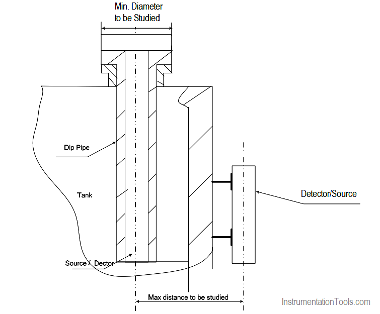
Figure – Nucleonic internal source/detector and external detector/source example
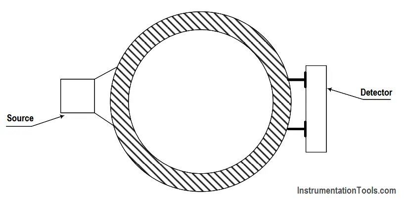
Figure – Nucleonic external source and detector example
Calibration and configuration
A nuclear system always needs to be calibrated in the field. For interface or profile applications, it is recommended to use two different media for the calibration.
A one or two point calibration method can be used to setup an interface/profiling application.
A one point calibration (e.g. with water) is more convenient if a vessel can only be filled with one defined homogeneous media. However, the interface measurement accuracy will depend on the difference between the lower and upper fluid density.
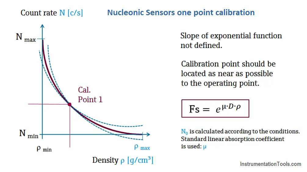
One point calibration
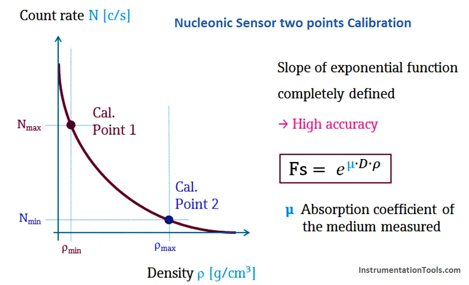
Nucleonic two points calibration
Calibration process
- perform background calibration (vessel absorption)
- switch OFF the radiation. Perform water (other media are possible if the density is known) calibration (1. Point): Ensure that the vessel is filled with water only. The water level should be at least at the height of the upper detector. Switch ON the radiation.
- switch OFF the radiation. Perform oil (other media are possible if the density is known) calibration (2. Point): Ensure that the vessel is filled with oil. The oil level should be at least at the height of the upper detector. Switch ON the radiation.
Source : International Association of Oil & Gas Producers
Acknowledgements : IOGP Instrumentation and Automaton Standards Subcommittee (IASSC), BG Group, BP, Endress + Hauser, Emerson, Honeywell, Krohne, Petrobras, PETRONAS Carigali Sdn Bhd, Repsol, Siemens, Statoil, Total, Vega, Yokogawa.