Inst ToolsInst ToolsInst Tools
  • Courses
  • Automation
    • PLC
    • Control System
    • Safety System
    • Communication
    • Fire & Gas System
  • Instrumentation
    • Design
    • Pressure
    • Temperature
    • Flow
    • Level
    • Vibration
    • Analyzer
    • Control Valve
    • Switch
    • Calibration
    • Erection & Commissioning
  • Interview
    • Instrumentation
    • Electrical
    • Electronics
    • Practical
  • Q&A
    • Instrumentation
    • Control System
    • Electrical
    • Electronics
    • Analog Electronics
    • Digital Electronics
    • Power Electronics
    • Microprocessor
  • Request
Search
  • Books
  • Software
  • Projects
  • Process
  • Tools
  • Basics
  • Formula
  • Power Plant
  • Root Cause Analysis
  • Electrical Basics
  • Animation
  • Standards
  • 4-20 mA Course
  • Siemens PLC Course
Reading: Capacitance Level Measurement Working Principle
Share
Font ResizerAa
Inst ToolsInst Tools
Font ResizerAa
  • Courses
  • Design
  • PLC
  • Interview
  • Control System
Search
  • Courses
  • Automation
    • PLC
    • Control System
    • Safety System
    • Communication
    • Fire & Gas System
  • Instrumentation
    • Design
    • Pressure
    • Temperature
    • Flow
    • Level
    • Vibration
    • Analyzer
    • Control Valve
    • Switch
    • Calibration
    • Erection & Commissioning
  • Interview
    • Instrumentation
    • Electrical
    • Electronics
    • Practical
  • Q&A
    • Instrumentation
    • Control System
    • Electrical
    • Electronics
    • Analog Electronics
    • Digital Electronics
    • Power Electronics
    • Microprocessor
  • Request
Follow US
All rights reserved. Reproduction in whole or in part without written permission is prohibited.
Inst Tools > Blog > How It Works > Capacitance Level Measurement Working Principle

Capacitance Level Measurement Working Principle

Last updated: September 14, 2016 5:47 pm
Editorial Staff
How It Works Level Measurement
No Comments
Share
5 Min Read
SHARE

Capacitance Level Measurement:

Capacitive level transducer is an example of indirect measurement of level

capacitance probe

Capacitance level sensors are used for wide variety of solids, aqueous and organic liquids, and slurries. The technique is frequently referredĀ  as RF as radio frequency signals applied to the capacitance circuit. The sensors can be designed to sense material with dielectric constants as low as 1.1 (coke and fly ash) and as high as 88 (water) or more. Sludges and slurries such as dehydrated cake and sewage slurry (dielectric constant approx. 50) and liquid chemicals such as quicklime (dielectric constant approx. 90) can also be sensed. Dual-probe capacitance level sensors can also be used to sense the interface between two immiscible liquids with substantially different dielectric constants.

Since capacitance level sensors are electronic devices, phase modulation and the use of higher frequencies makes the sensor suitable for applications in which dielectric constants are similar.

Working Principle:

The principle of capacitive level measurement is based on change of capacitance. An insulated electrode acts as one plate of capacitor and the tank wall (or reference electrode in a non-metallic vessel) acts as the other plate. The capacitance depends on the fluid level. An empty tank has a lower capacitance while a filled tank has a higher capacitance.

Ā A simple capacitor consists of two electrode plate separated by a small thickness of an insulator such as solid, liquid, gas, or vacuum. This insulator is also called as dielectric.

Value of C depends on dielectric used, area of the plate and also distance between the plates.

capacitance equation

Where:

C = capacitance in picofarads (pF)

E = a constant known as the absolute permittivity of free space

K = relative dielectric constant of the insulating material

A = effective area of the conductors

d = distance between the conductors

This change in capacitance can be measured using ACĀ bridge.

Measurement:

Ā 
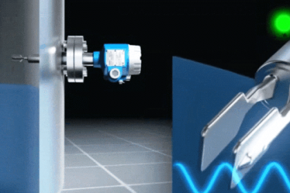
Measurement is made by applying an RF signal between the conductive probe and the vessel wall.

The RF signal results in a very low current flow through the dielectric process material in the tank from the probe to the vessel wall. When the level in the tank drops, the dielectric constant drops causingĀ  a drop in the capacitance reading and a minute drop in current flow.

This change is detected by the level switch’s internal circuitry and translated into a change in the relay state of the level switch in case of point level detection.

In the case of continuous level detectors, the output is not a relay state, but a scaled analog signal.

Ā Level Measurement can be divided into three categories:

  • Measurement of non-conductive material
  • Measurement of conductive material
  • Non-contact measurement

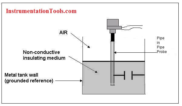
Non-conducting material:

For measuring level of non conducting liquids, bare probe arrangement is used as liquid resistance is sufficiently high to make it dielectric. Since the electrode and tank are fixed in place, the distance (d) is constant, capacitance is directly proportional to the level of the materialĀ  acting as dielectric.

Conducting Material:

In conducting liquids, the probe plates are insulated using thin coating of glass or plastic to avoid short circuiting. The conductive material acts as the ground plate of the capacitor.

Proximity measurements (Non-contact type measurements):

In Proximity level measurement isĀ  the area of the capacitance plates is fixed, but distance between plates varies.

Proximity level measurement does not produce a linear output and are used when the level varies by several inches.

Advantages of Capacitive level measurement:

  1. Relatively inexpensive
  2. Versatile
  3. Reliable
  4. Requires minimal maintenance
  5. Contains no moving parts
  6. Easy to install and can be adapted easily for different size of vessels
  7. Good range of measurement, from few cm to about 100 m
  8. Rugged
  9. Simple to use
  10. Easy to clean
  11. Can be designed for high temperature and pressure applications.

Ā Applications:

Capacitance Level Probes are used for measuring level of

  1. Liquids
  2. Powered and granular solids
  3. Liquid metals at very high temperature
  4. Liquefied gases at very low temperature
  5. Corrosive materials like hydrofluoric acid
  6. Very high pressure industrial processes.

Disadvantages:

Light density materials under 20 lb/ft3Ā and materials with particle sizes exceeding 1/2 in. in diameter can be a problem due to their very low dielectric constants (caused by the large amount of air space between particles).

Don't Miss Our Updates
Be the first to get exclusive content straight to your email.
We promise not to spam you. You can unsubscribe at any time.
Invalid email address
You've successfully subscribed !

Continue Reading

Electromagnetic Flow Meters Working Principle
DP Diaphragm Capillary Seal Level instrument Calibration Procedure
Float Level Switch Working Principle
Servo Tank Gauges Working Principle
Air Purge or Air Bubbler Level Measurement
Overview of Tank Gauging Technologies
Share This Article
Facebook Whatsapp Whatsapp LinkedIn Copy Link
Share
Leave a Comment

Leave a Reply Cancel reply

Your email address will not be published. Required fields are marked *

Stay Connected

128.3kFollowersLike
69.1kFollowersFollow
210kSubscribersSubscribe
38kFollowersFollow

Categories

Explore More

Level Gauge Design
Cable Float Level Switch Working Principle
Displacer Interface Level Measurement
Magnetostrictive Level Measurement
Float Level Switch Working Principle Animation
Basic Working Principle of Vortex Flowmeter
Types of Industrial Level Sensors
Tilt Level Switch Working Principle

Keep Learning

torque tube displacement level transmitter

Level Troll working principle

Flow Switch Working Principle Animation

Working Principle of Flow Switch with Animation

Nuclear Level Measurement

Nuclear Level Detectors Cascade or Master/Slave concept

Closed Tank Level Measurement Formula

Siemens Differential Pressure Transmitter Calculations (Flange Type)

Closed Tank Remote Seal Level Transmitter calculation

Remote Seal Transmitters Ranging Calculation

Wet Leg Level Transmitter

Basics of DP Level Measurement

Dip Tape

What is Dip Tape Level Measurement?

NDIR GAS ANALYSER WORKING PRINCIPLE ANIMATION

NDIR Gas Analyser Working Principle

Learn More

McLeod Gauge Working Principle

McLeod Gauge Working Principle

Selecting the Best Inductive or Capacitive Sensor

Selecting the Best Inductive or Capacitive Sensor

Power Electronics Objective Questions

3 Phase Bridge Inverter MCQ

Force Balance Pressure Transmitters

PneumaticĀ Pressure Transmitters Principle

Electrical-Switches-Working-Animation

Difference between Star and Delta Connections

Digital Electronics Multiple Choice Questions

Triggering of Flip Flops Objective Questions

Power Factor Meter Principle

Power Factor Meter Principle

Token Ring Communication

Token Ring and Token Bus Working Animation

Menu

  • About
  • Privacy Policy
  • Copyright

Quick Links

  • Learn PLC
  • Helping Hand
  • Part Time Job

YouTube Subscribe

Follow US
All rights reserved. Reproduction in whole or in part without written permission is prohibited.
Welcome Back!

Sign in to your account

Username or Email Address
Password

Lost your password?