In this article, you will learn the general view of Instrumentation and control activities and documents for project packages in the detail engineering company.
As already mentioned, one of the great activities of I&C specialists in Detail Design Company is related to purchasing suitable Packages (Equipment) based on project requirements and in compliance with other project items and process operations.
Instrumentation Project Packages
The originator of these packages (for purchasing) usually are other technical departments (Rotary Equipment, Process, Mechanic, …) but they need the Instrumentation and Control (I&C) help for part of the package. Since different packages have different I&C blocks, the size and type of required activities are changing in many items.
In fact, I&C specialists shall specify different packages of projects at the initial stages by studying them and preparing suitable models for each.
Figure-4 shows one of the complex models for complicated packages (Turbo-Compressor) which may be used for defining a general overview of the package scope of supply of items and interfaces to project I&C blocks. It should be noticed that the package will be installed in one location of the plant (and maybe on the skid) while it shall be in accordance with other equipment or devices in the project.
On the other hand (usually) all required utility items of the package (including electrical power, instrument air, steam, water, …) shall be supplied by the project plan while the package vendor has no responsibility for them or the required paths outside of the package (skid) are out of scope of them.
In a similar case (usually) all required cabling and relevant routes for transferring the signals or communication links are outside of the package vendor. So, if the battery limits of scope were clear on the provided model (at the first stages), the project progress will be easily/ smoothly accessible without any ambiguity or discussion on possible claims.
Sometimes the battery limits of scopes will be discussed during the kick-off meeting and finalized results will be reflected on the proposed model.
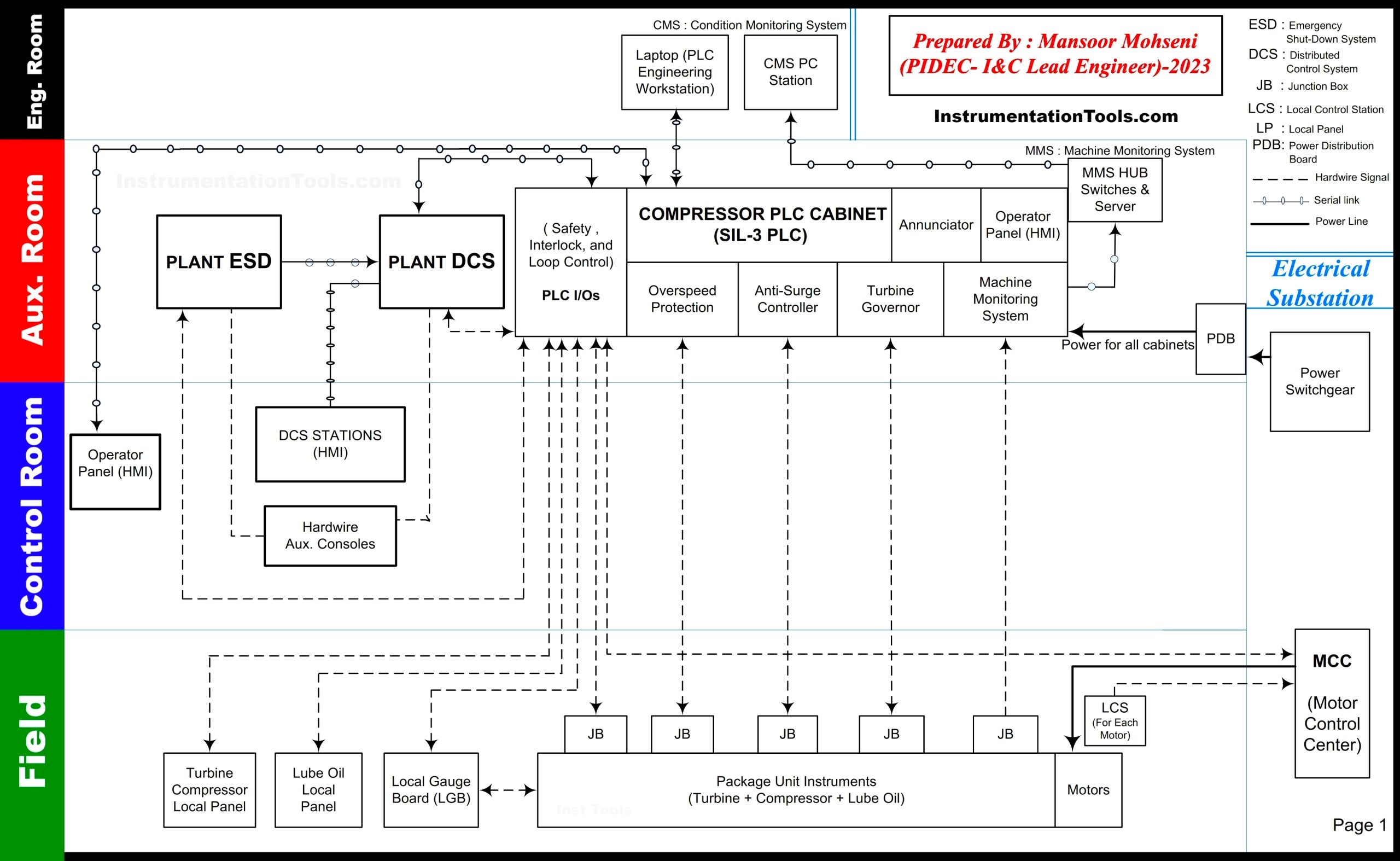
Figure-4: Package Interfacing Diagram (For Turbo-Compressor)
Further to battery limits clarification the required documentation and sequence of producing them shall be clarified during the kick-off meeting. The requested information and data by the client shall be reflected in vendor documentation accordingly. In order to receive the results quickly, using some diagram models can be very useful.
Package Instruments Documentation
Figure-5 shows one issue model of package documentation (RFD = Required For Documentation) which makes an easy tool for reaching common understandings on the target of required documents for all parties.
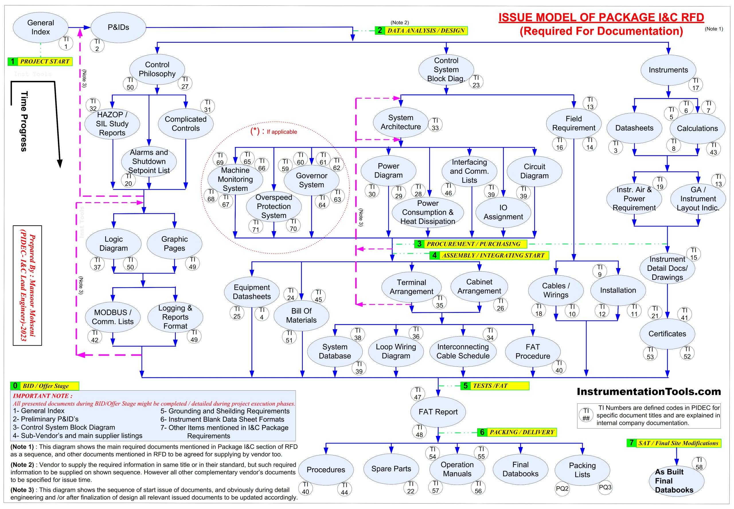
Figure-5 : Issue Model of Package I&C RFD (Required For Documentation)
As it is clear from Figure-5 the model can be provided generally for all packages and to be finalized during the kick-off meeting. As an example, it was clear on the model that generally all packages don’t have Machine Monitoring or Overspeed Protection Systems, and such items on the case of existence are to be discussed.
During the kick-off meeting both parties (Detail Engineering Company as client or purchaser and Vendor) shall make a common understanding of project requirements as much as possible and in this regard, some complementary diagrams or sketches can help such a goal (even the complementary items may seem very evident.
Package Vendors
Figure-6 shows one of such simple diagrams to show a model for transferring interactions/ information between both parties and logically describes the required inputs for following project steps.
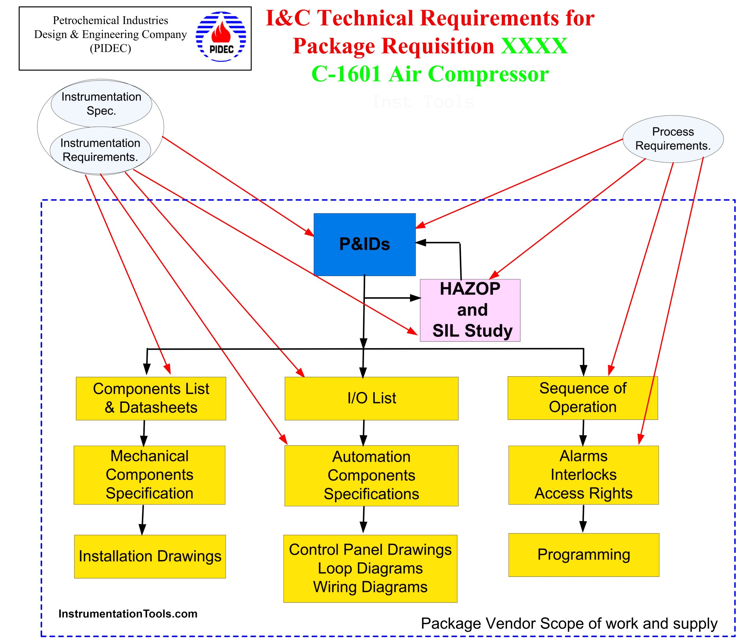
Figure-6: Overview Sequence of Information Flow for producing Detailed Documents by Package Vendor
Usually in providing the documentation some abbreviations are used which may produce big problems in some cases (especially if the domain of using the abbreviations is similar).
Abbreviations
For example, MMS can be used for Machine Monitoring System or for Maintenance Management System, and both are applicable for rotary equipment packages while they refer to two dedicated separate subjects. If such abbreviations were not defined clearly, may cause some claim discussions during the project’s progress. So, defining any abbreviations or company codes shall be done. Figure-7 shows a sample of defining abbreviations and company codes.
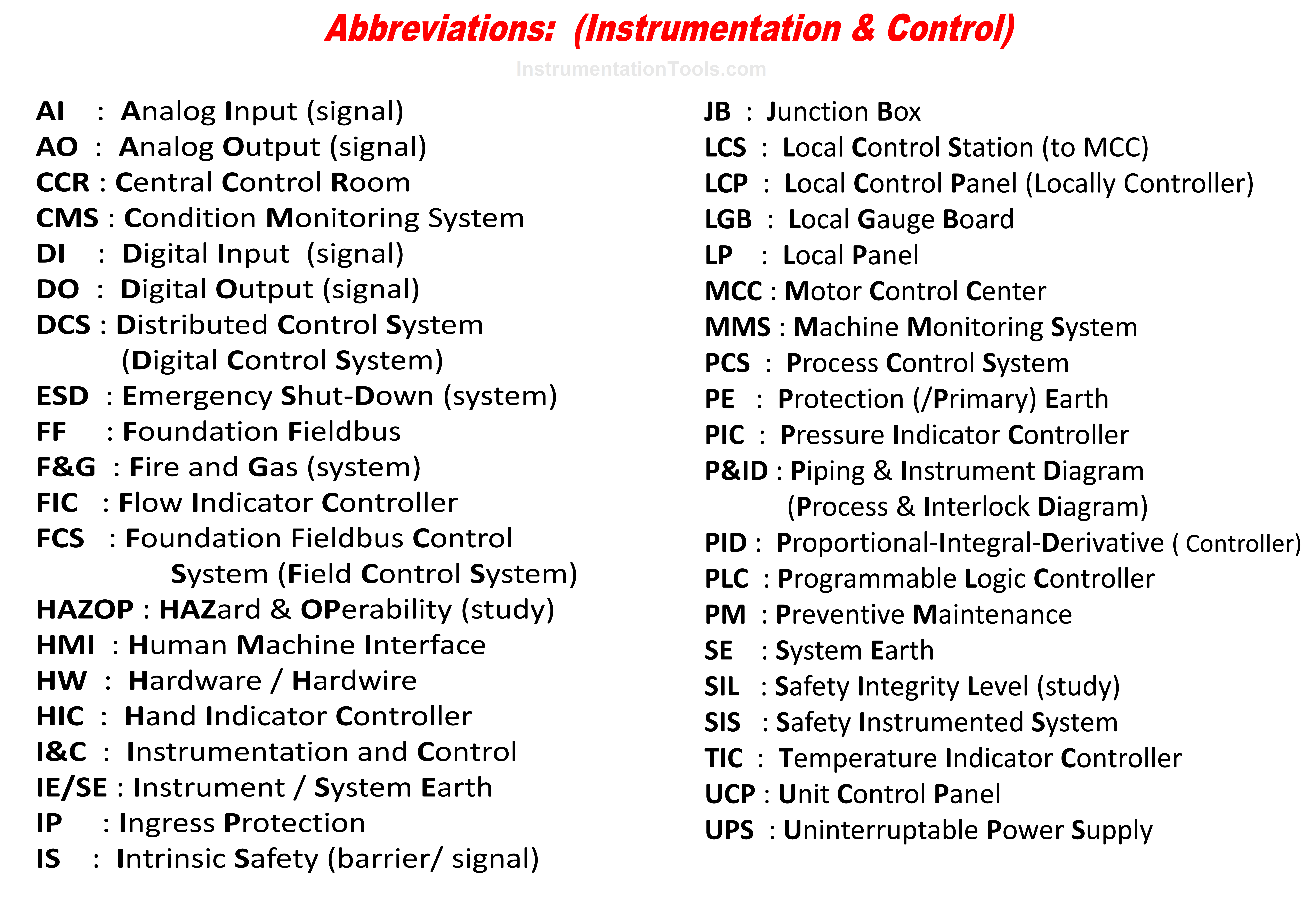
Figure-7: Sample of Abbreviations Definitions and Company Document Codes
Figure-7 shows some predefined checklists as samples that can help the I&C engineer responsible for the package.
I&C Engineer in Detail Engineering Company
The I&C engineer (of Detail Engineering Company) first of all shall be very familiar with project requirements and consider conditions for process control and safety systems in order to caring uniformity/ similarity of package I&C parts with project ones. On the other hand, he/she shall make uniformity in function operations further to consider instruments as much as possible.
In this regard, HMI graphic displays, Logic Interlocks, and some special considerations (like RESET, Maintenance Override Switches, Emergency philosophy, MCC signal interfacings, …) shall be discussed with the package vendor to reach the project approach as much as possible.
Secondly, the I&C engineer who is responsible for the package shall have enough information and knowledge about that, in order to understand all special cases of that package. Otherwise requesting or insisting on some items which are not applicable to that package may cause some problems, or in the reverse case, missing the available facilities of the package may produce unconformity with the project approach.
The third, I&C engineer who is responsible for the package shall be familiar with available technologies and different approaches of vendors on that dedicated package. In fact, I&C engineer shall know that some package vendors hire sub-vendors for their I&C parts, while some others have their own I&C specialists for implementing I&C parts. Some of them are using special dedicated I&C parts, while some others have the facility of selecting I&C parts from different sub-vendors.
There are many other items that may be counted for skills of the I&C engineer responsible for the package, but in order to wrap up this subject and as a summary such specialists shall be good knowledge of I&C parts of the project and package, and also have enough experience.
In fact, such I&C specialist shall follow some training for package requisitions and also uses some company-prepared checklists to take care of preventing missing any required items.
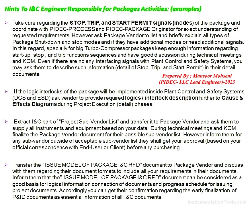
Figure-8: Sample Checklist for I&C Engineer responsible for Package
Instrumentation Project
| Phase | Activities | Documents |
|---|---|---|
| Conceptual Design | Requirement analysis, feasibility studies, initial control system design. | Requirement analysis, feasibility studies, and initial control system design. |
| Preliminary Design | Conceptual design reports, initial project plans, and feasibility study reports. | Detailed design of the control systems, safety analysis, and cost estimates. |
| Detailed Design | Preliminary design reports, process and instrumentation diagrams (P&IDs), safety analysis reports, and initial cost estimates. | Finalizing control system design, selecting and sizing instruments, creating detailed P&IDs, and programming control logic. |
| Construction/Installation | Detailed design reports, finalized P&IDs, instrument data sheets, control logic diagrams, interconnection diagrams, and instrument location plans. | Overseeing installation of control systems, collaborating with suppliers and contractors, and initial system testing. |
| Commissioning | Installation plans, vendor documentation, testing protocols, and field inspection reports. | Conducting comprehensive system testing, system tuning, training operators, and resolving any installation or functioning issues. |
| Operation and Maintenance | Continuous system monitoring, troubleshooting, system upgrades, and maintenance. | Documenting lessons learned, final project reporting, and decommissioning. |
| Project Closure | Commissioning reports, system testing results, and operator training manuals. | Operation and maintenance manuals, incident reports, system upgrade plans, and maintenance records. |
Conclusion
At the end of this article, it is reminded again that I&C specialists have different roles and positions in project executions, and by their activities, documents, and co-ordinations a vital part of the project will be followed.
However, most of these roles and positions shall have some common abilities and some special ones and in order to study their actions, I&C engineer of Detail Engineering Company is a good choice.
In 3 parts of this article, we were familiar with some of the approaches that shall be followed by such I&C engineers.
Instrumentation Detail Design Phase:
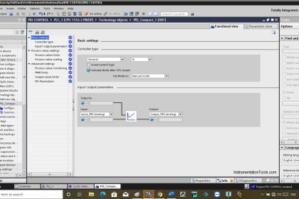
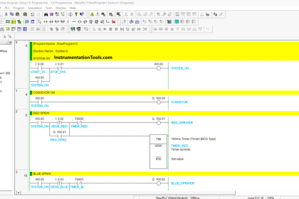
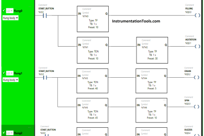



Following most DCS models and having built a few Process Plants for both Chemical and Utility Processing, there is a Major DCS Interface that we would label the Network Room where the Interfaces include Radio, Fiber Panels and Local Comm Links. Most PLC controllers were Localized at distances greater than 10 km with their own Electrical and Communications Buildings.
THEN instead of a Control Room they were called Operator Control Rooms where DCS Redundant Hardware sits underneath Tables loaded with KVM interfaces (usually 30 or more Visual Screens including Dynamic Security screens).
Power Gen Systems were separated from Business System interfaces were separated from Process Systems were separated from Security and specialized Utility and Transportation Systems. All Integrated through various Interfaces not accessible to the outside world.