Inst ToolsInst ToolsInst Tools
  • Courses
  • Automation
    • PLC
    • Control System
    • Safety System
    • Communication
    • Fire & Gas System
  • Instrumentation
    • Design
    • Pressure
    • Temperature
    • Flow
    • Level
    • Vibration
    • Analyzer
    • Control Valve
    • Switch
    • Calibration
    • Erection & Commissioning
  • Interview
    • Instrumentation
    • Electrical
    • Electronics
    • Practical
  • Q&A
    • Instrumentation
    • Control System
    • Electrical
    • Electronics
    • Analog Electronics
    • Digital Electronics
    • Power Electronics
    • Microprocessor
  • Request
Search
  • Books
  • Software
  • Projects
  • Process
  • Tools
  • Basics
  • Formula
  • Power Plant
  • Root Cause Analysis
  • Electrical Basics
  • Animation
  • Standards
  • 4-20 mA Course
  • Siemens PLC Course
Reading: Instrument Numbering Philosophy
Share
Font ResizerAa
Inst ToolsInst Tools
Font ResizerAa
  • Courses
  • Design
  • PLC
  • Interview
  • Control System
Search
  • Courses
  • Automation
    • PLC
    • Control System
    • Safety System
    • Communication
    • Fire & Gas System
  • Instrumentation
    • Design
    • Pressure
    • Temperature
    • Flow
    • Level
    • Vibration
    • Analyzer
    • Control Valve
    • Switch
    • Calibration
    • Erection & Commissioning
  • Interview
    • Instrumentation
    • Electrical
    • Electronics
    • Practical
  • Q&A
    • Instrumentation
    • Control System
    • Electrical
    • Electronics
    • Analog Electronics
    • Digital Electronics
    • Power Electronics
    • Microprocessor
  • Request
Follow US
All rights reserved. Reproduction in whole or in part without written permission is prohibited.
Inst Tools > Blog > Instrumentation Design > Instrument Numbering Philosophy

Instrument Numbering Philosophy

Instrument numbering philosophy is important factor while preparing P&ID and other documents related to instruments and follows ISA 5.1

Last updated: June 10, 2021 12:33 pm
Editorial Staff
Instrumentation Design
No Comments
Share
5 Min Read
SHARE

Instrument Numbering is one of the most important factors that have to be considered while preparing P&ID and other documents related to instruments.

Contents
Instrument Tagging PhilosophyUnit NumberInstrument TypeLoop Numbering

Instrument Tagging Philosophy

Instrument Numbering Philosophy

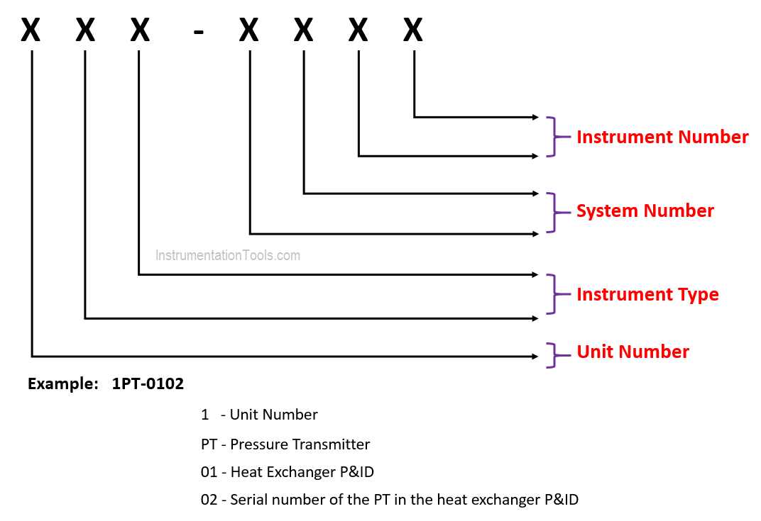
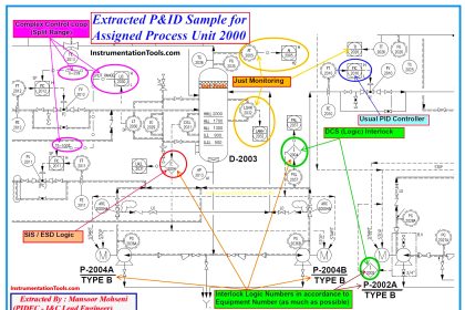
The above image shows the basic structure of Instrument Numbering Philosophy.

It includes

  • Unit Number
  • Instrument Type
  • System Number
  • Instrument Number

Unit Number

It indicates the plant, area and unit in which the instrument is located

Use basic number if project is small, there are no area, unit or plant number

Eamples: PT-1 or PT-01 or PT-001

If project has a few areas, units or plants, then the first number of instrument number indicates plant number

Example: PT-102 is an instrument located in plant 1

If project is big and is divided into areas, units or plants, a  prefix is added before instrument type.

New Tag Number

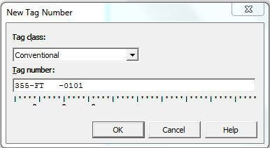
Example: 355-FT-0101 is an instrument located in area 3, unit 5 and plant 5.

Here 0101 indicates the loop number associated with the instrument

Instrument Type

Each instrument associated within an instrumented facility ought to have its own unique identifying tag comprising of a series of letters depicting that instrument’s function.

The naming of instrument type is usually done by taking ISA 5.1 as reference.

Below table indicates some of the instrument types. 

S.No.Type of InstrumentSymbol
1Pressure GaugePI
2Temperature GaugeTI
3Level GaugeLI
4ThermocoupleTE(K)
5RTDTE
6Pressure TransmitterPT
7Temperature TrarsmlitterTT
8Level TransmitterLT
9Flow ElementFE
10Flow TransmitterFT
11Pressure SwitchPS
12Differential Pressure SwitchDPS
13Differential Pressure Indicating SwitchDPIS
14Differential Pressure TransmitterDPT
15Temperature SwitchTS
16Temperature Indicating SwitchTIS
17Level SwitchLS
18I/P ConverterI/P
19Position TransmitterZT
20Control ValveCV

Refer ISA 5.1 for more instrument types

Loop Numbering

System number and instrument number together called as loop number of an instrument

Loop number depicts the loop associated with an instrument and it should be helpful while creating loop drawings.

As per ISA 5.1 loop numbering may be parallel or series.

According to ISA 5.1, in parallel loop numbering, a process variable letter is coupled with a number to make the unique identifier.

  • Accordingly, there might be a TIC-101, PIC-101 & LIC-101 since T101, P101 & L101 are unique and parallel.
  • Each of those three letter and number sets define a different loop; they may be related, but they are unique.
  • This numbering system can be used effectively when  the number is linked to a piece of equipment, like a pump, where all the loops associated with pump101 would carry that number within the tags as listed above.

As per ISA 5.1, In serial numbering, they are using a unique numerical sequence for each loop without the process variable modifier, one number for each loop.

  • Accordingly, there might be TIC-101, LR-102 and PIC-103, but not an TIC-101 and PIC-101 since the pressure and temperature variables will get each a different number.
  • This is the simplest system to use and it is therefore probably the most common.

Finally, the numbering system chosen for your P&IDs and loops should be tested and confirmed to guarantee that it works as expected with the various software applications used in your facility. Loop number 1 and loop number 001 will have markedly different by some data sets and by the maintenance planning and inventory control software.

Author: Greeshmesh TP

If you liked this article, then please subscribe to our YouTube Channel for Instrumentation, Electrical, PLC, and SCADA video tutorials.

You can also follow us on Facebook and Twitter to receive daily updates.

Read Next:

  • SIL Verification
  • What is SAMA Diagram?
  • What is FAT and SAT?
  • Ferrules and Cross Ferruling
  • Instrumentation Design Engineer
Don't Miss Our Updates
Be the first to get exclusive content straight to your email.
We promise not to spam you. You can unsubscribe at any time.
Invalid email address
You've successfully subscribed !

Continue Reading

How to Select the Right Panel Enclosure for Your Application?
Transmitter Detailed Specifications
Instrumentation Role during Steam Blowing
Heat Tracing Problems
Instrument Panel Cooling Efficiency Enhancement
Temperature Gauges and Elements : Detailed Specifications
Share This Article
Facebook Whatsapp Whatsapp LinkedIn Copy Link
Share
Leave a Comment

Leave a Reply Cancel reply

Your email address will not be published. Required fields are marked *

Stay Connected

128.3kFollowersLike
69.1kFollowersFollow
210kSubscribersSubscribe
38kFollowersFollow

Categories

Explore More

Tagging Philosophy for Junction Box, Cable, and Cable Drum
How to Select Right Thermocouple & Thermowell ?
Load Cell Design
What is Instrument DataSheet ?
Instrumentation Cable trays Installation in vertical orientation
Electrical and Instrumentation – Automation Pre-engineering Documents
Magnetic Flow Meters Installation Guidelines
Field Instruments Scaling and Unit Conversions

Keep Learning

Air Cylinder Consumption Calculation for Control Valves

Air Cylinder Consumption Calculation for Control Valves

How to Select a pH and ORP Meter

How to Select a pH or ORP Meter

Relay Motor Logic Circuit

Motor Control Circuits

Pressure Regulators vs Pressure Control Valves

Pressure Control Valves vs Pressure Regulators

Determine the statuses of all lamps and relay coils in the circuit

Determine the Status of Lamps and Relays in the Circuit ?

Motor ladder Logic

Draw a ladder logic circuit for the electric motor of an air compressor ?

LCS Configuration equipped with LOTO Facility

Motor Control Signal Interface

What is NEST loading in DCS

What is Nest Loading? – DCS and PLC Control Systems

Learn More

Multi Way Switches using PLC

Making Multi Way Switches using PLC

Free WinCC SCADA Training Course

Free SCADA Training Course

Analog Electronics Objective Questions

Analog Electronics Objective Questions – Set 10

Elevated Span and Suppressed Span

DP Level Transmitter Elevation and Suppression Corrections

Thermocouples Burnout detection

Thermocouples Burnout detection

Ammonia Analyzer Working

Ammonia Analyzer Principle

Loop Diagram

PT Loop Diagram Faults

PLC Automation Memory

What is NOR Flash Memory in PLC?

Menu

  • About
  • Privacy Policy
  • Copyright

Quick Links

  • Learn PLC
  • Helping Hand
  • Part Time Job

YouTube Subscribe

Follow US
All rights reserved. Reproduction in whole or in part without written permission is prohibited.
Welcome Back!

Sign in to your account

Username or Email Address
Password

Lost your password?