Feedback obtained from industrial users of FF reveal a common pattern: Fieldbus is a powerful and reliable technology, but only if it is properly installed. Poor installations, usually driven by a desire to minimize capital expenses, will cause numerous problems during commissioning and operation.
One relatively easy way to avoid problems caused by short-circuits in FF wiring is to use coupling devices with built-in short-circuit protection. This feature does not add significant cost to the coupling device, and it will prevent the entire segment from failing due to a short-circuit on a single spur cable or within a device. Use coupling devices with indicator LEDs as well, since these give easy visual verification of network power which may greatly accelerate FF segment troubleshooting when the need arises.
Cable resistance
A simple check of an H1 segment’s cabling consists of a series of resistance measurements performed with the segment unpowered (as is standard with any electrical resistance check), with all FF devices disconnected, and with the cable entirely disconnected (all three conductors) at the host end.
The following table shows guidelines published by the Fieldbus Foundation for H1 segment cable resistance measurements:
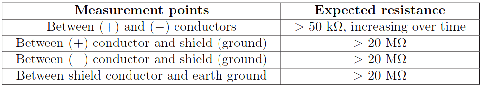
The last resistance check shown in the table checks for the presence of ground connections in the shield conductor other than the one ground connection at the host end (which has been disconnected for the purposes of the test). Since the shield should only be grounded at one point (to avoid ground loops), and this one point has been disconnected, the shield conductor should register no continuity with earth ground during the test.
The necessity of disconnecting all FF devices and host system interfaces is essential so that the resistance measurements reflect the health of the cable and nothing else. The presence of any FF devices on the segment would substantially affect the resistance measurements, particularly resistance between the signal (+ and −) conductors.
Note : An alternative method of shield grounding is to directly connect it to earth ground at one end, and then capacitively couple it to ground at other points along the segment length. The capacitor(s) provide an AC path to ground for “bleeding off” any induced AC noise without providing a DC path which would cause a ground loop.
Signal strength
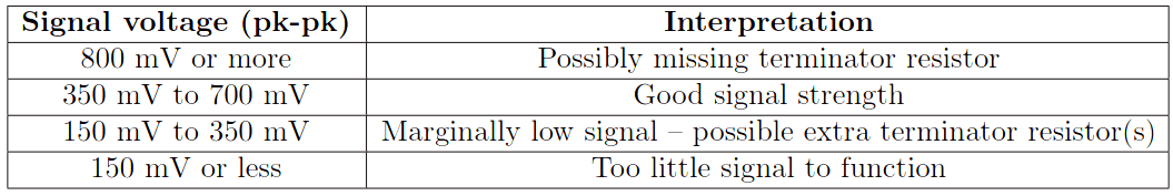
The Fieldbus Foundation specifies a signal voltage (peak-to-peak) range of 350 mV to 700 mV for a healthy FF segment. Excessive signal voltage levels point to a lack of terminator resistor(s), while insufficient voltage levels point to an over-abundance of terminators (or perhaps even a device short):
Electrical Noise
FF, like all digital networks, are unaffected by noise voltage below a certain threshold. If noise voltage is present in excessive quantity, though, it may cause bits to be misinterpreted, causing data errors. The Fieldbus Foundation gives the following recommendations for noise voltage levels on a FF segment:
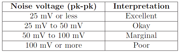
Fieldbus diagnostic tools measure noise on the network segment during times between message frames, when there should be purely DC voltage between the two conductors.
Note : Bear in mind the tolerable level for noise will vary with signal voltage level as well. All other factors being equal, a strong signal is less affected by the presence of noise than a weak signal (i.e. the signal-to-noise ratio, or SNR, is crucial).
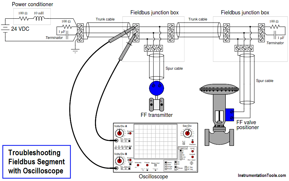
Using an oscilloscope on H1 Fieldbus segments
A tool available in most instrument shops is a digital-storage oscilloscope, which may be used to measure and display FF H1 signal waveforms for analysis of problems. Analog oscilloscopes are also useful for network troubleshooting, but to a lesser degree .
When using an oscilloscope to measure FF H1 signals, it is very important not to connect either of the FF segment conductors to earth ground through the oscilloscope. Introducing such a “ground fault” to the network segment will almost certainly cause communication problems, in addition to whatever problems already exist that compel you to diagnose with an oscilloscope. If a single channel of the oscilloscope is connected across the segment wires, the “ground” clip of the probe will force one of those conductors to earth ground potential via the metal chassis of the oscilloscope which is grounded through the third prong of the power plug for safety. An exception to this rule is if the oscilloscope itself is battery-powered and has an insulated case where no ground connection is made through the surface it sits on or the human hand that holds it. Otherwise, using a single channel on a line-powered oscilloscope to measure network signals is inviting trouble.
If a line-powered oscilloscope must be used, the proper way to configure it is for differential channel measurement. In this mode, the oscilloscope will register the voltage between two probe tips, rather than register the voltage between a single probe tip and earth ground.
Configuring a dual-trace oscilloscope for differential mode is quite simple. On the front panel of the oscilloscope, you must set the multi-trace controls to the Add mode, where one trace on the screen represents the instantaneous sum of the two inputs (channels “A” and “B”). The volts per division “sensitivity” of both channels should be set to exactly the same value.
Also, the Invert control must be engaged for the second input channel, forcing that channel’s signal to be inverted (register upside-down on the screen). The summation of channel “A” and an inverted channel “B” is equivalent to the mathematical difference (subtraction) between “A” and “B,” which means the single trace on the screen now represents the difference of potential between the two probe tips. The oscilloscope now behaves as an ungrounded voltmeter, where neither of the test leads is referenced to earth ground.
Message re-transmissions
Aside from voltage parameters (signal strength, noise amplitude), another good indicator of FF segment health is the number of message re-transmissions over time. Certain types of communication on an H1 segment require verification of a received signal (particularly client/server VCRs such as those used to communicate operator setpoint changes and diagnostic messages). If the signal received by the client FF device appears corrupted, the device will request a re-transmission of the message from the server device. Re-transmission events, therefore, are an indication of how often messages are getting corrupted, which is a direct function of signal integrity in a Fieldbus segment.
Most host systems provide re-transmission statistics in much the same way that computers communicating via TCP/IP protocol have the ability to display the number of “lost” data packets over time. Since nearly all FF segments function with a host system connected, this becomes a built-in diagnostic tool for technicians to troubleshoot FF network segments.
Hand-held diagnostic tools are also manufactured to detect signal voltage levels, noise voltage levels, and message re-transmissions.


Excellent knowledge site
Sir your articles are very good sir I need a profiebus communication which help me in field so plz send me that material sir