Earthing / Grounding and Bonding is one of the most important subjects (especially for Electrical and I&C Engineering Teams) in all industrial process plants. This subject may be implemented in different ways due to understanding ambiguities of combining different standards’ requirements in a common way. However, there are some good practices that exist, and in this article we try to investigate one of them based on common Industrial Process Plants Earthing Requirements.
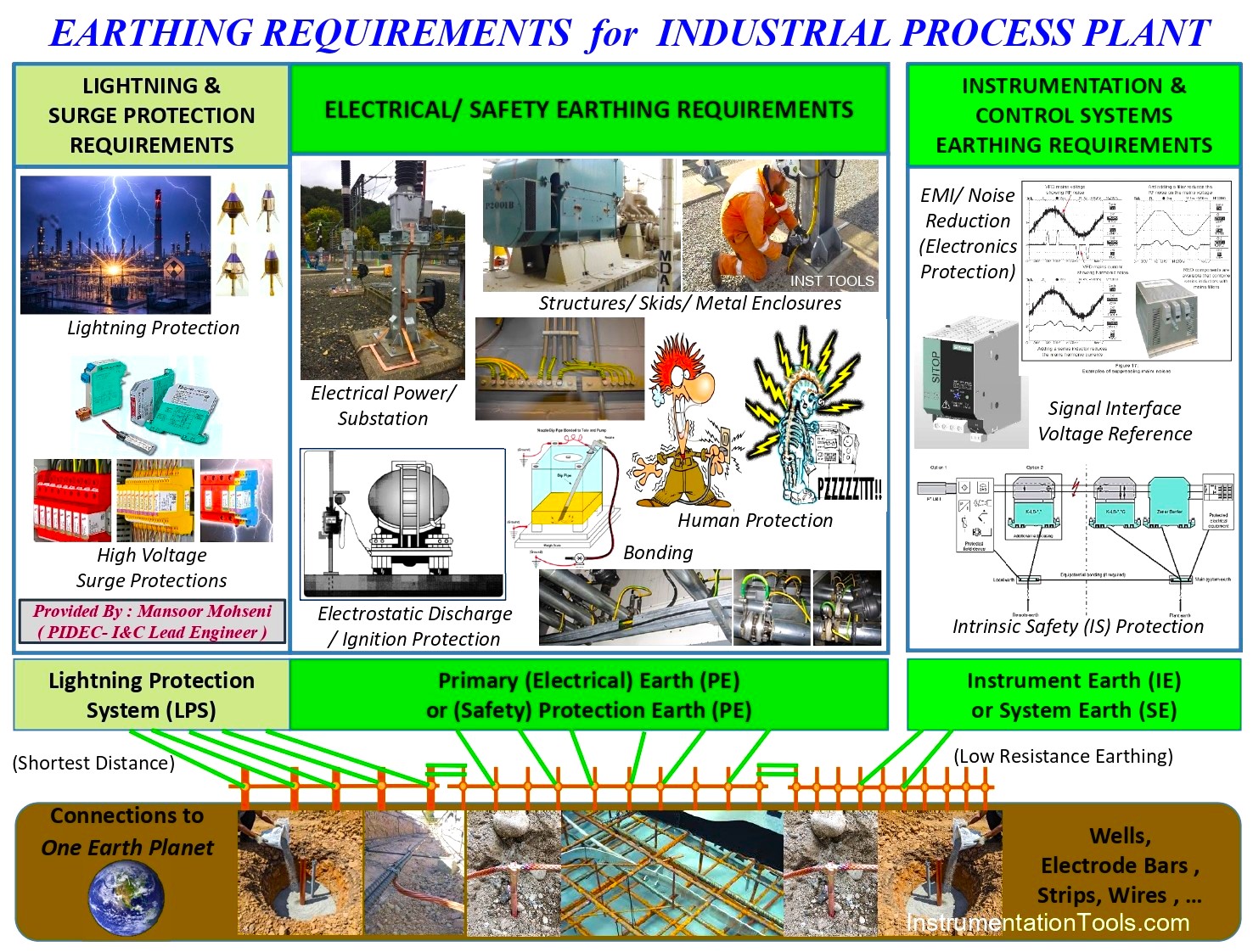
FIG-1: Summary View of Earthing Requirements for Industrial Process Plant.
Earthing Requirements for Automation Industries
Industrial Process Plants need different types of requirements and Earthing aspects which can be studied and investigated in different standards, guidelines, books, and articles in detail (see some article references at the end).
In order to investigate the good proposed practice, we first mention here just some of the main Earthing Requirements (extracted from the reference article):
- To provide a path for power system fault currents to flow back to the source of supply, and to mitigate arc flash hazards.
- The elimination of electric shock hazards (touch and step voltages).
- To provide a path to dissipate lightning currents into the general mass of the Earth.
- The elimination of ignition hazards, whether related to Ex-certified apparatus or the prevention of the interruption of stray currents.
- The dissipation of electrostatic charges that could cause potentially incendive sparking.
- To ensure the integrity of signal return paths, and to minimize electrical interference with such signals.
Earthing/grounding/bonding systems are important for electrical safety, lightning safety, and the control of sources of potential ignition. They contribute to the operability of process control systems and to the integrity of active safety functions; hence these systems make a vital contribution to continuity of operation and to ongoing asset integrity.
Types of Earthing systems
The integrity of such requirements for implementation in a good practice way is our target, and as FIG-1 shows, we classified them into three main Earthing systems:
- Electrical Power/ Safety (Primary) Protection Earthing System (PE)
- Lightning Protection System (LPS)
- Instrumentation & Control Systems Earthing (IE or SE).
As FIG-1 shows, all Earthing system requirements will be implemented on just one earth (planet), but the I&C Earthing Requirement block is considered slightly separated from the other two. This is because I&C Earthing Systems need (very) low-resistance electrical paths to earth (usually called clean) in comparison to the other two requirement blocks. Hereby, FIG-1 shows that such a condition may be implemented by using a more earth rod (/wells) network (/mesh), even at shorter distances in limited areas (usually around control buildings or electronic systems installation areas).
The important point which is not clearly shown in FIG-1 is that the three main Earthing systems will be implemented by a network of earth rods (/wells) in a two-dimensional pattern on the earth surface, and the location of earth rods (/wells) is not necessarily on one direct line. These earth rods (/wells) may be interlaced with each other’s for different earthing networks/systems too (this will be clarified at the end of this article).
Noting the above clarification is very important to find why three different earthing systems are connected to each other’s (in limited point(s)) to make equipotential surface earth (systems), while they can satisfy different earthing requirements and conditions (even different resistance earthing systems). On the other hand, the limited connection point(s) of three different earthing systems will be one of the main characteristic conditions of our target model.
In addition, referring to FIG-1, it should be mentioned that the enclosures of electronic systems and AC Mains feeders for control panels (which are related to I&C equipment) need Electrical Protection Earthing requirements too, while they will be satisfied by the middle block of FIG-1.
Some Good Practice Models for Implementing Industrial Process Plant Earthing
Let us start our study for good earthing practice by reviewing some of the proposed models, which are very near to this article’s target. FIG-2 shows a very good practice model for the summary result of the combination of requirements proposed by MTL Instruments Group PLC (in May 1997).
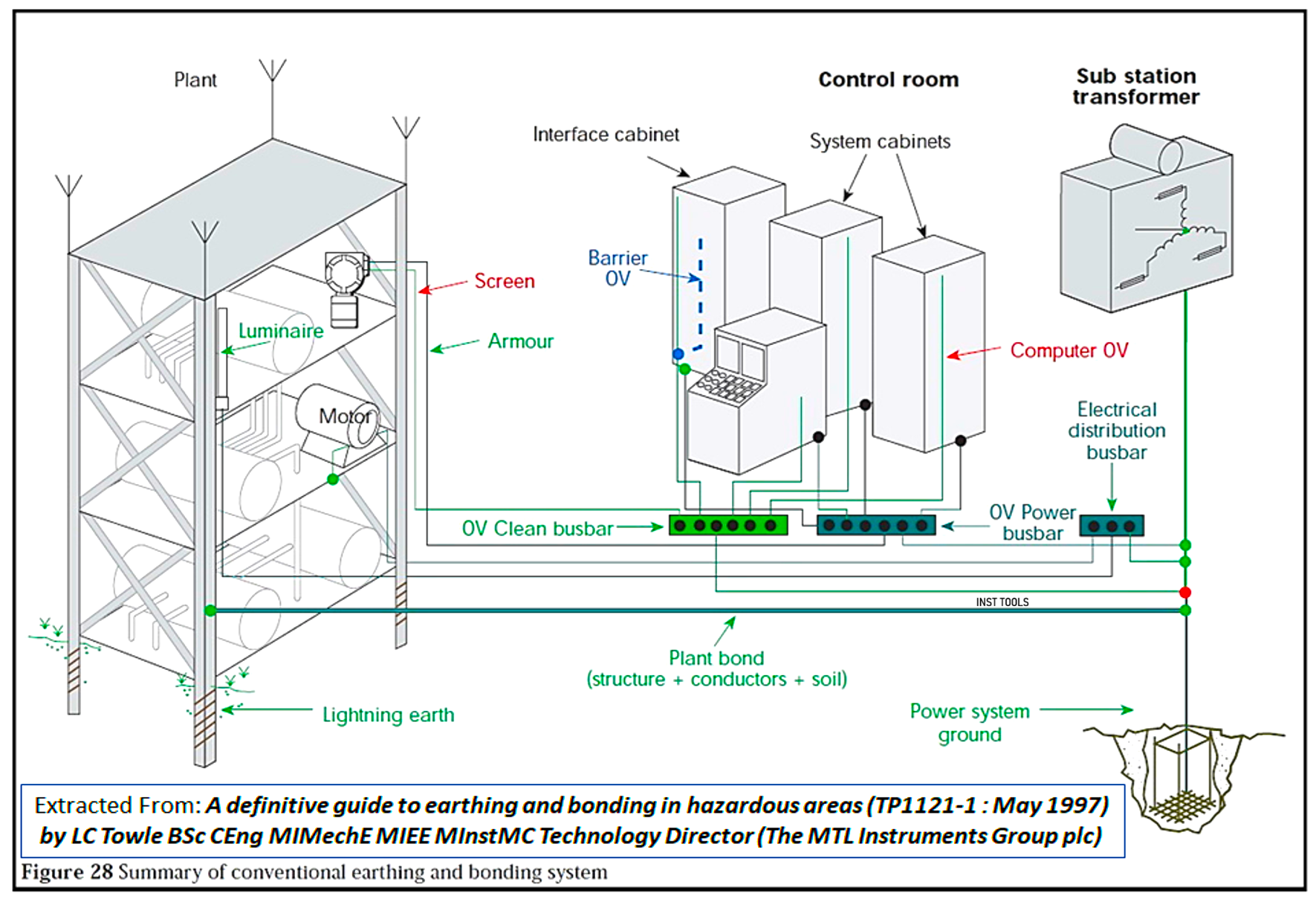
FIG-2: Summary of Conventional Earthing and Bonding System (proposed by MTL Instruments Group PLC- May 1997).
This model shows the connection of three different Earthing Systems to one Earth point. As you can see from FIG. 2, the enclosures of I&C items are connected to the 0V Power busbar with the same electrical distribution busbar earth legend shape (and color). Also, please notice that the I&C Earthing busbar is called 0V Clean (which means a low-resistance earthing path). Furthermore, you can see that the lightning protection system will be transferred to earth (planet) by the shortest paths, although it is connected to the power system ground too.
This model has very good, clear indications for different earthing system requirements, but it is not so clear for (how) the exact implementation of different paths and earthing networks in practice. Notice that single-point connections to power system ground (= earth planet) will not clarify exactly the differences between different paths’ requirements (including resistances).
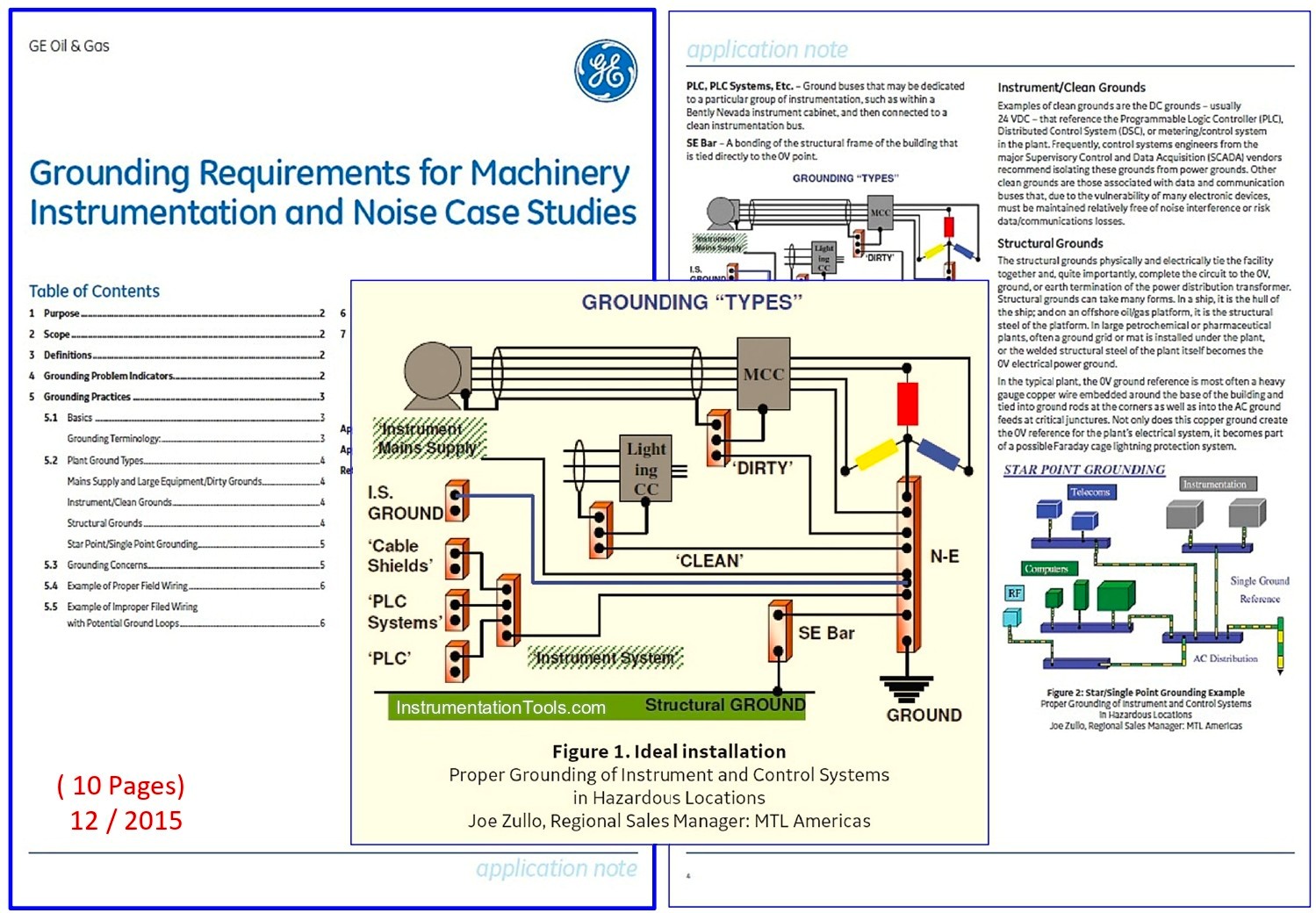
FIG-3: Another model for Summary of Conventional Earthing and Bonding Systems (proposed by Joe Zullo in GE Oil & Gas Application Note).
FIG-3 shows another model for the summary of conventional earthing and bonding systems, which is proposed by Joe Zullo – MTL (and used in GE Oil & Gas Application Note -2015). This model is very similar to the previous one, with the same configuration and positive and weak points. However, as it is clear from the title of the Application Note (Grounding Requirements for Machinery Instrumentation and Noise Case Studies), it is more useful for clarifying I&C Earthing Requirements (since it has more details on I&C Earthing items).
FIG-4 shows another similar earthing model, which is explained in a good reference book. Further to the I&C earthing system focus, it has more detailed considerations on Intrinsic Safety (IS) Earth Bars too. Generally, we may say that such IS Earth requirements were required in the case of using Zener Diode Isolation Barriers (in the past), but nowadays, by using the galvanic isolators, our IS Earthing requirements can be satisfied by a normal I&C (Electronic) Earthing System (IE or SE).
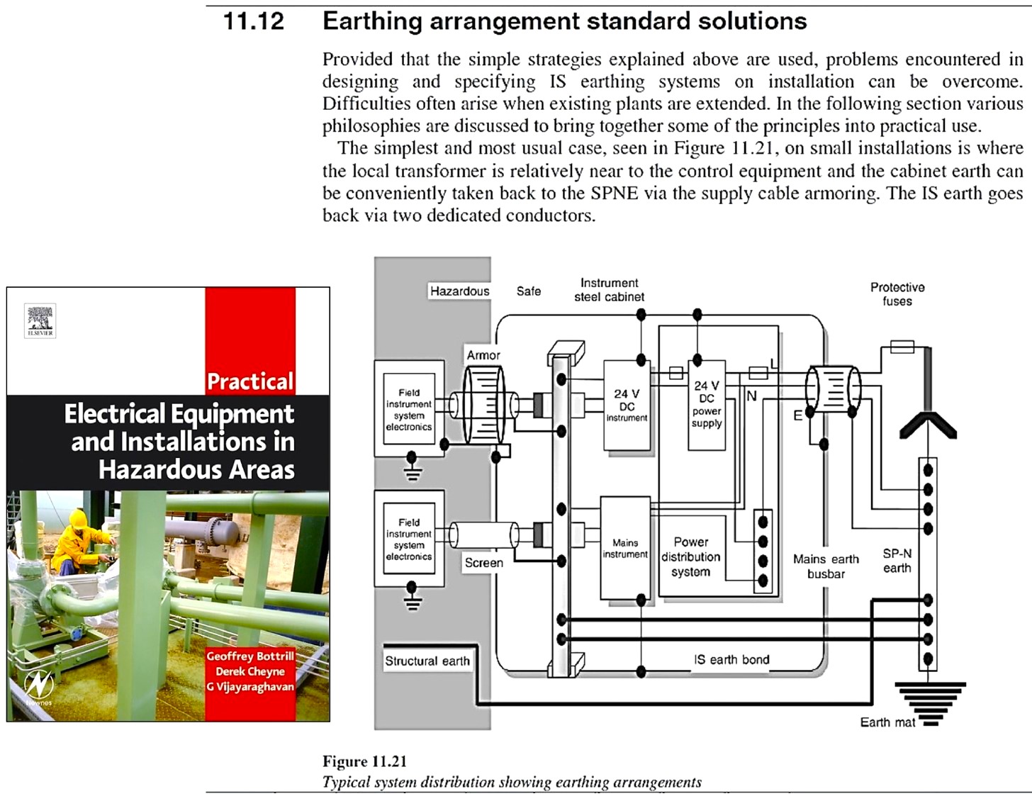
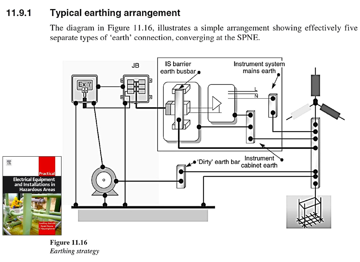
FIG-4: A very good reference book (Practical Electrical Equipment and Installations in Hazardous Area) shows another good Earthing Model
A Good Practice for Implementing Earthing
Now we propose the new good practice model which satisfies most (approximately all) of the earthing requirements in an industrial process plant (summarized in FIG-1), and is very similar to the other above-mentioned models.
This model is shown in FIG-5. As FIG-5 shows, this model is prepared based on three main Earthing Systems (i.e., Electrical Primary/ Protection Earthing, I&C (Electronic) Earthing, and Lightning Protection), which all have an equipotential (voltage) level by connection at earth wells head (/electrodes).
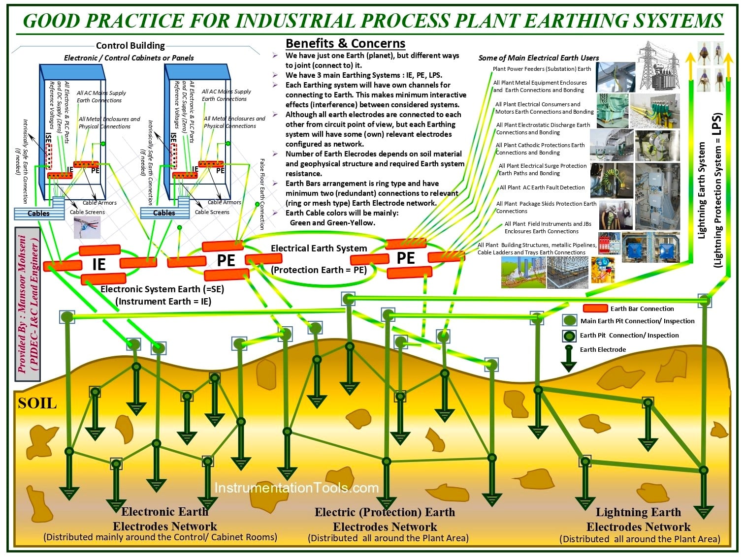
FIG-5: A Good Practice for Industrial Process Plant Earthing Systems.
As FIG-5 shows, this model has the following benefits and concerns:
- We have just one Earth (planet), but with different ways to join (connect to) it.
- We have 3 main Earthing Systems: IE, PE, LPS.
- Each Earthing system will have its own channels for connecting to Earth. This minimizes interactive effects (interference) between the considered systems.
- Although all earth electrodes are connected from a circuit point of view, each Earthing system will have some (own) relevant electrodes configured as a network.
- The number of Earth Electrodes depends on soil material and geophysical structure and required Earth system resistance.
- The earth bar arrangement is ring type and has a minimum of two (redundant) connections to the relevant (ring or mesh type) Earth Electrode network.
- Earth Cable colors will be mainly Green and Green-Yellow.
A Realistic Project Based on Good Earthing Practice Model
FIG-6 shows a sample schematic model for implementation of Earthing systems (in an actual and realistic project) based on the above proposed good practice model.
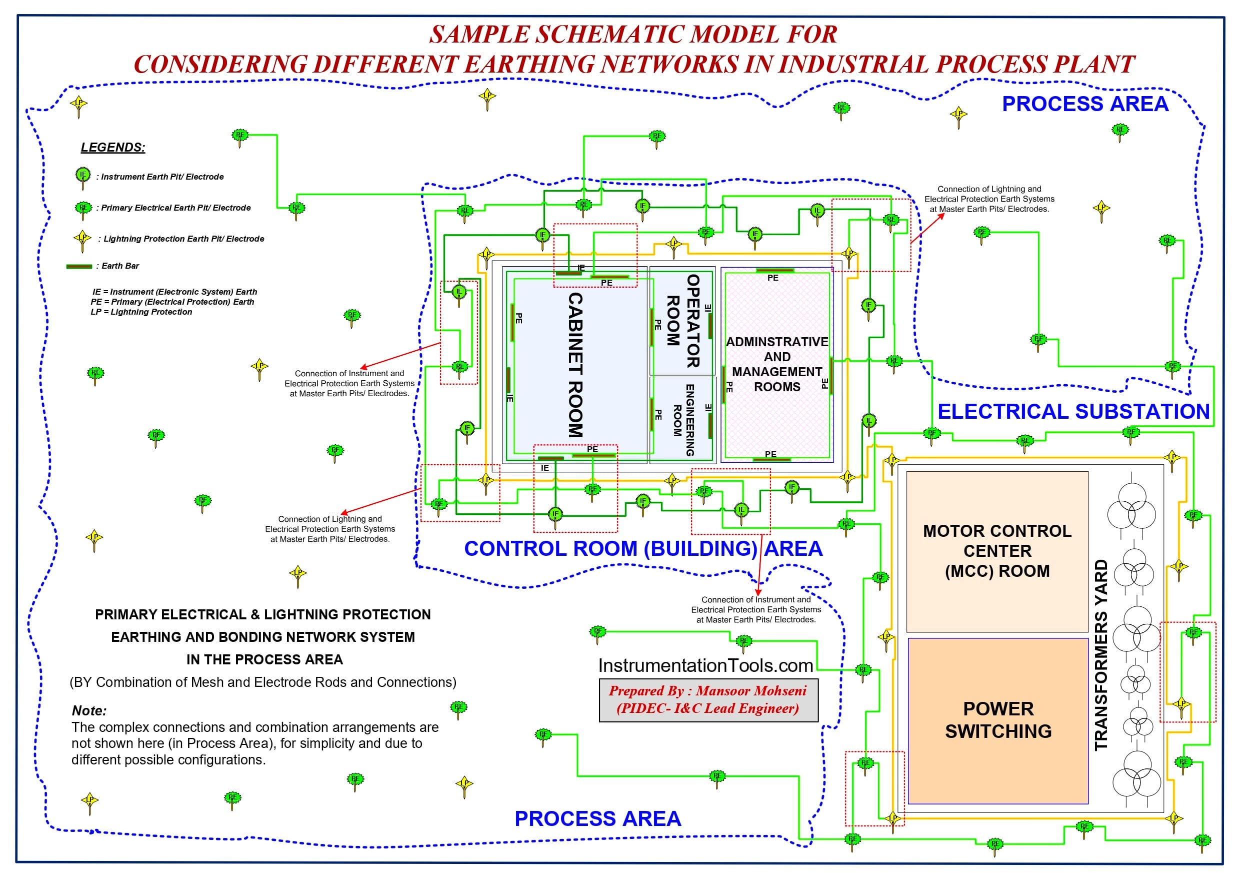
FIG-6: Sample Schematic Model for considering different Earthing Networks in an Industrial Process Plant (based on proposed good practice).
Notice that the three main Earthing Systems (Networks) are arranged and combined with each other based on the proposed good practice model (shown in FIG-5).
Although this schematic model will provide good basics for effective satisfaction of Earthing Requirements in Industrial Process Plant, further to this arrangement, some important concerns need to be considered for the right and correct implementation of the whole system.
30 Concerns for Right Implementing Good Practice Earthing
GENERAL:
- Define the suitable legends in all project documents for each (3) types of Earthing Connections. Clear identification of each earth system in the project documents will have great positive effects on finding the right earthing concepts and hence minimize future possible problems.
- Use the proper dedicated color for the physical wiring of each type of (3) earthing system. This will make easily trace each earthing system throughout the project area exactly, and especially prevents the wrong connection wiring to the desired systems (see FIG-5).
If you use (or have used) just one wire color for (3) earthing systems, it is very important to at least highlight/indicate I&C Earthing system (IE or SE) wirings, by proper way (for example, by using tapes on such wires at defined distances and especially at the end connection destinations).
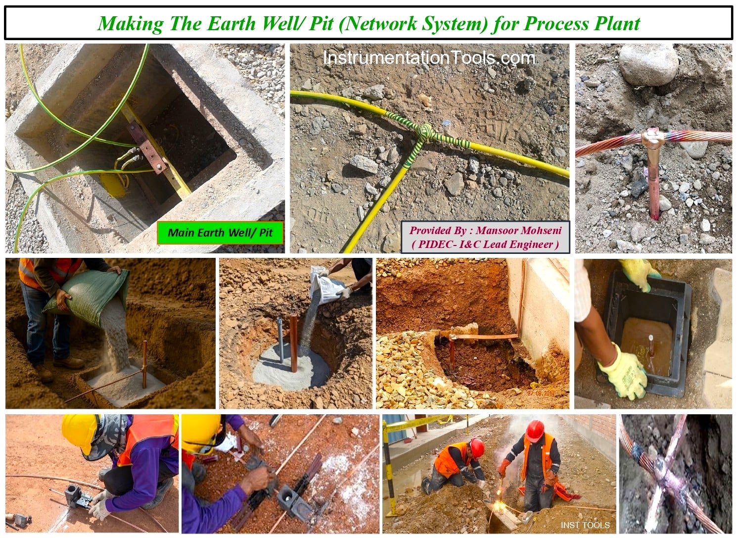
FIG-7: Making The Earth Well/Pit (Network System) for Process Plant
- All Earthing target systems shall be connected to each other just at the Earth Wells Network level. On the other hand, do not connect different Earth Bars (belonging to different systems) above the earth pits/wells surfaces. This will ease future troubleshooting for isolating the earth bars to find the points of problems (further to minimize wrong circuit currents). (see FIG-7)
- I&C Earthing system shall be connected to the Electrical Safety Earthing system just at limited ways (one or two) at Earth Pits/Wells level. Using two ways will guarantee the continuity of connection, but more than two will have some effects on the considered dedicated systems.
- If you use the Earth Bars connection as a ring type, you will have the redundancy facility to guarantee the continuity of connection to a suitable earthing system target. (see FIG-5)
- Usually, I&C Earth Pits/Wells are considered around the control room (building) area, while it would be better to distribute or locate the relevant ones interlaced between Electrical Earth Pits/Wells (see FIG-6).
- The required quantity and distribution of Electrical Safety and Lightning Protection Earth Pits/Wells around the project site will be specified by considering relevant standards and requirements (See FIG-6).
- The number of required Earth Pits/Wells for each earthing system will be specified by studying and testing the project ground surfaces and soil materials. Since for the I&C Earthing system we need very low resistance, usually the accumulation of such relevant Earth Pits/Walls at the specified area will be more than for other systems (see FIGs 5 and 6). In some projects, the quality of such Earth Pits/Walls (or even areas) may be enhanced by proper tricks.
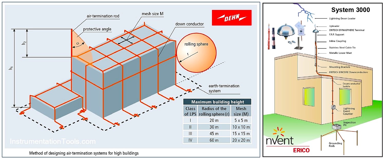
FIG-8: Shortest Path Consideration for Lightning Protection System, further to other enhancement considerations.
Lightning Protection System (LPS)
- Lightning Earth path shall be connected to the Earth Pit/Well with the shortest distance, with a low-resistance earth rod facility and suitable conductor size (see FIG-8).
- The location of required LPS head (dome) for buildings and equipment and the required quantities and distances between Air Terminals shall be specified by relevant standards and practices (see FIG-9).
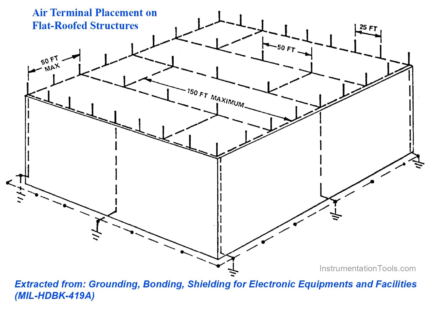
FIG-9: One Good Practice for Air Terminal Placement on Flat-Roofed Structure.
- It is recommended to have no direct connection between LPS and the I&C Earthing system (IE or SE), but instead they will be at the same equipotential voltage level via the electrical protection system (PE) as shown in FIG 5 and 6. This will provide more protection for sensitive electronic systems and circuits.
- Surge Protection System through reducing levels sequence shall be considered for I&C (Electronic) systems by using suitable Surge Protection Devices (SPD), which are installed for sensitive or at-risk instruments and circuits and at the entrance of control system cabinets/ panels (if required). See FIG-1 again for using such Surge Protection Devices. However, notice that using such devices needs exact understanding of the required Earthing systems and enough knowledge for selecting and using a sequence of down voltage-level devices.
Electrical/Safety Protection Earth (PE)
It should be noted that the Electrical/ Safety Protection Earthing system is considered mainly due to plant power feeders/substation, so it is recommended to consider one PE Earth bar at each electrical (distribution) panel (see FIG-10).

FIG-10: Considering Protection Earth Bar (PE) inside The Power Distribution Panel.
- All plant AC Earth Fault detection shall be connected to Electrical/Safety Earth Bars.
- All equipment enclosures and relevant earth connections and bonding shall be connected to Electrical/Safety Earth Bars distributed around the project site.
- All plant electrostatic discharge earth connections and bonding shall be connected to Electrical/Safety Earth Bars distributed around the project site.
- All plant cathodic protection earth connections and relevant bonding shall be connected to Electrical/Safety Earth Bars distributed around the project site.
- All plant electrical surge protection earth paths and bonding shall be connected to Electrical/Safety Earth Bars distributed around the project site.
- All plant package skids protection earth connections and bonding shall be connected to Electrical/Safety Earth Bars distributed around the project site (see FIGs 11 and 12).
- All plant electrical consumers and motors protection earth connections and bonding shall be connected to Electrical/Safety Earth Bars distributed around the project site (See FIGs 11 and 12).
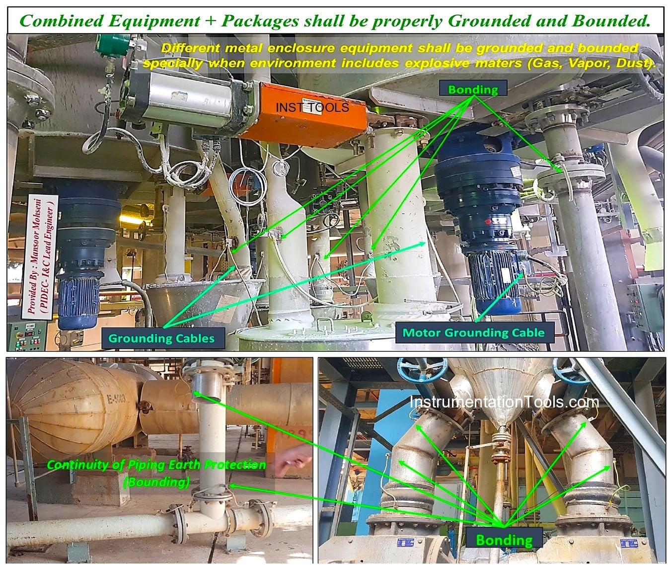
FIG-11: Combined Equipment + Packages Earth Protection (=Grounding) and Bonding.
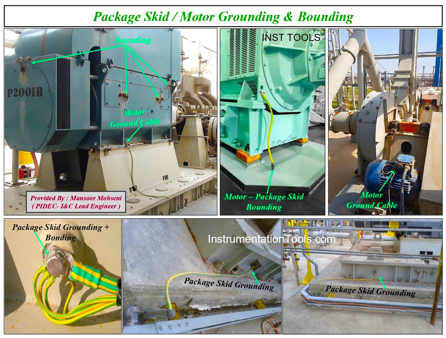
FIG-12: Package Skid / Motor Earth Protection (=Grounding) and Bonding
- All plant field instruments and Junction Boxes (JBs) enclosures earth protection and bonding shall be connected to Electrical/Safety Earth Bars distributed around the project site.
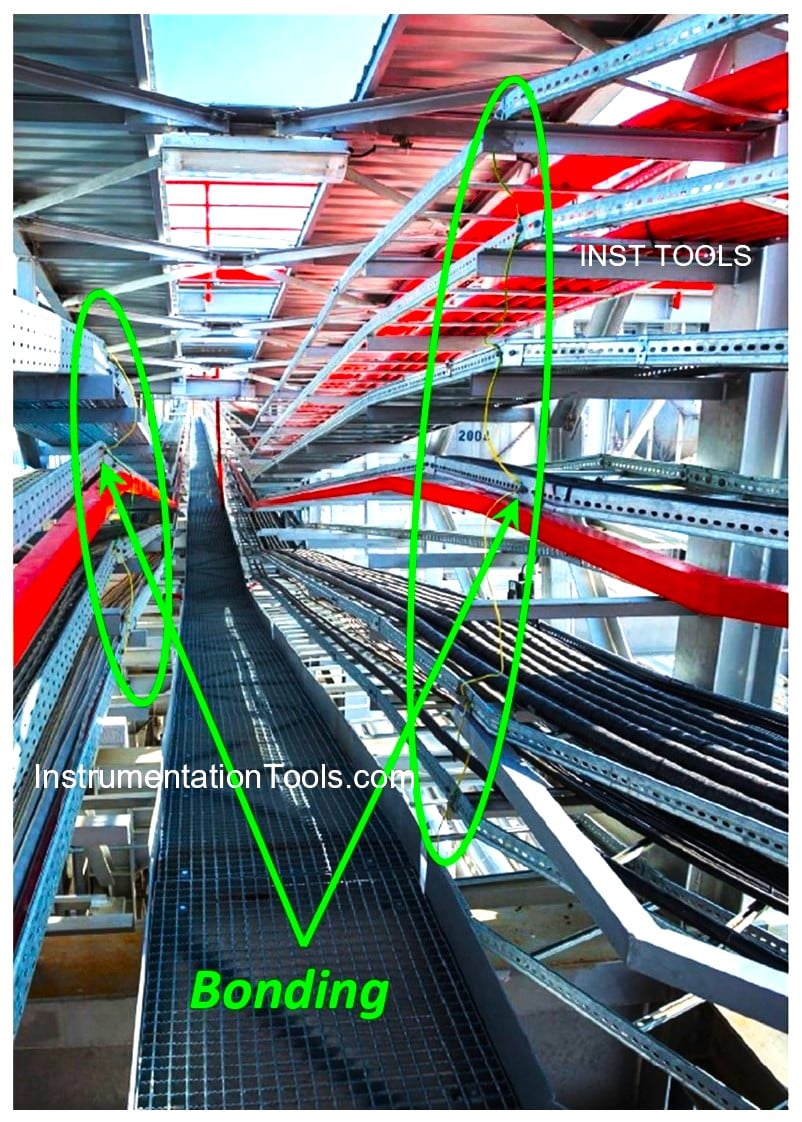
FIG-13: Cable Ladders & Trays shall be properly bonded and connected to Electrical/ Safety Earth Protection Bars distributed around the project site.
All plant building structures, metallic pipelines, cable ladders, and trays earth connections and bonding shall be connected to Electrical/Safety Earth Bars distributed around the project site (see FIG-13).
Instrumentation & Control Systems Earths (IE/SE + PE)
Instrumentation and Control (I&C) Earth Requirements are provided by two rings of Earth Bars inside the control room or building, normally called IE/SE and PE, as shown in FIGs 5, 6, and 14. These Earth Bar Rings are isolated from each other and are connected to relevant Earth Pits/ Wells via redundant connection cables.
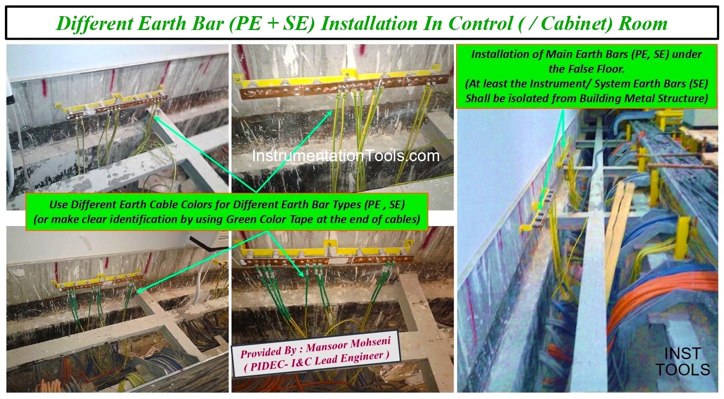
FIG-14: Different I&C Earth Requirements inside Control Room/ Building.
- All Electronic & PLC/ Control Systems Parts and DC Supply (Zero) Reference Voltages shall be connected to IE/SE Earth Bar installed in Cabinets and Panels and isolated from enclosure (and PE). (See FIG-5).
- All Screens and Armors of I&C Cables shall be connected to IE/SE and PE Earth Bars, respectively. (See FIGs 5 and 15).
- All metallic parts of cabinet enclosures and equipment (inside the cabinet) shall be connected to the PE Earth Bar and properly bonded. (See FIGs 5 and 14, 16).
- Provided under the False Floor Earth Mesh (practice for enhancing EMI protection) shall be connected to the PE Earth Bar ring inside the control room/ building, further to the building metallic structure. (See FIGs 5 and 17).
- During the Factory Acceptance Test (FAT) and always during the Project Site Checking of Control and Safety Systems Cabinets, be sure that the IE/SE Earth Bars are isolated from the metal enclosure and PE. Similar checking is to be done for IE/SE Ring Earth Bars inside the control room or building. Of course, for each mentioned test, the upstream connection to Earth Pits/ Wells shall be disconnected.
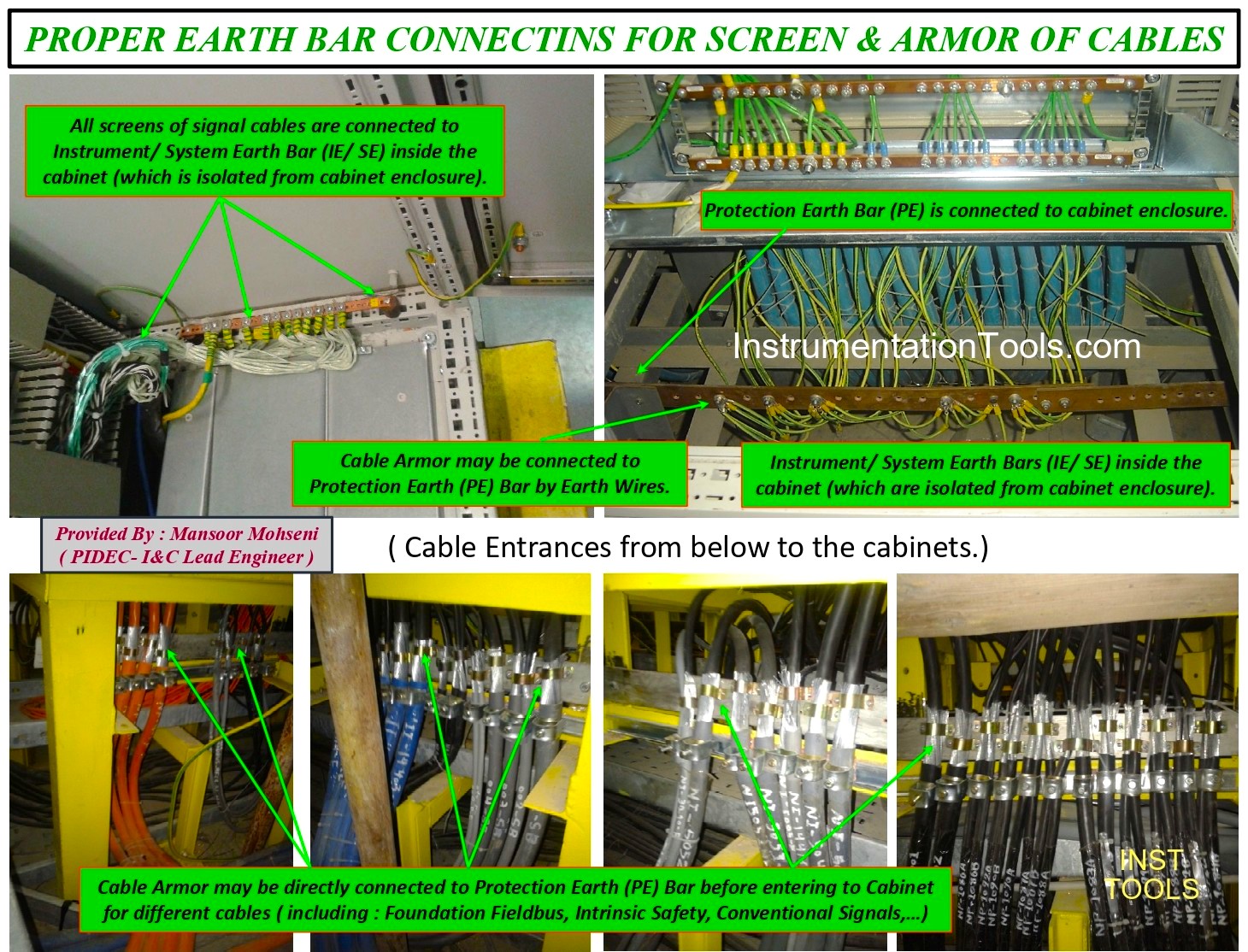
FIG-15: Connection of Screen and Armor of I&C cables to relevant Earth Bars.
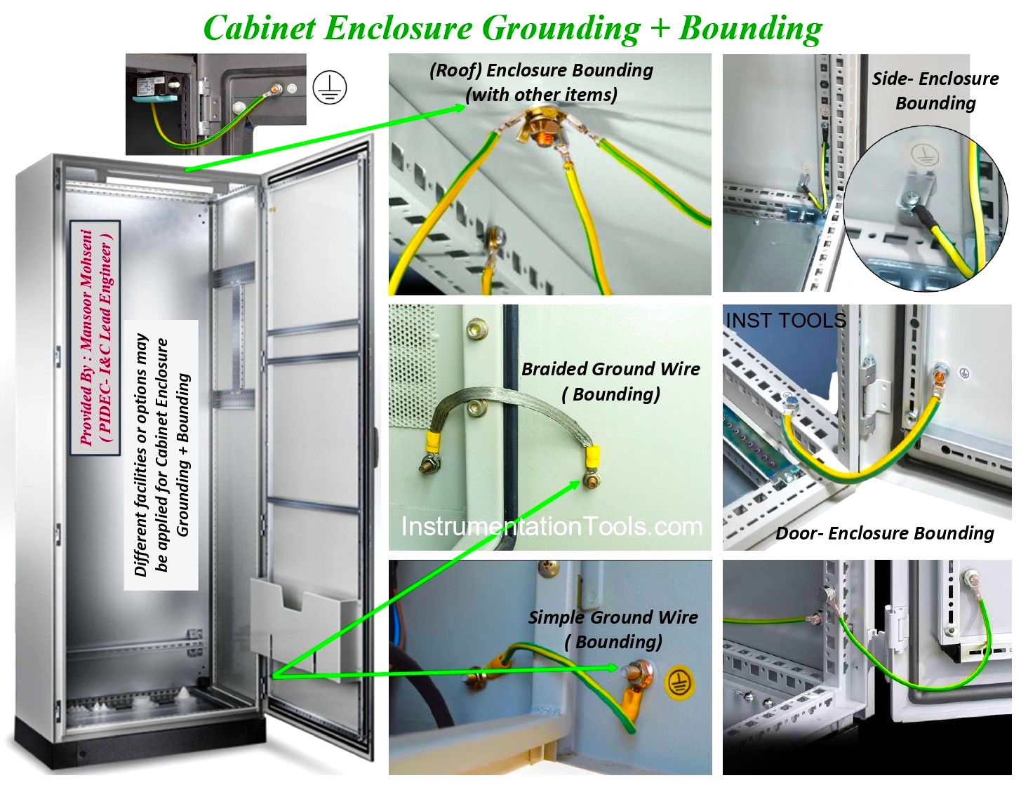
FIG-16: Cabinets/Panels Enclosure Parts Connection to Earth (PE) and Bonding.
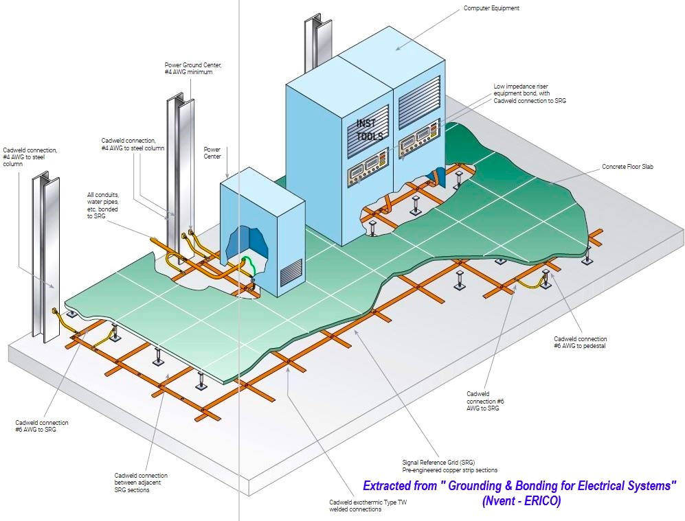
FIG-17: Under the False Floor Mesh Connection to Earth (PE) and Bonding.
- Intrinsic Safety Earth Bar or ISE (if required inside the cabinets) shall be connected to IE/SE Earth Bars inside the control room or building. Nowadays, due to the use of Galvanic Isolator Barriers no need for using, such separate Earth Bar (See FIGs 5 and 18). As API RP-12 Recommended Practice shows, such ISE may be connected to the IE/SE Earth Bar (See FIG-18 for different possible earth configurations).
- Finally, it shall be mentioned that the good practice model configuration proposed by this article may be found in different formats in some famous companies too. FIG-18 shows one example of such a similar configuration which was found in HP documents. As FIG-19 shows, the IE/SE Earth system is connected to the Electrical/Safety Earth System (PE) at only one point, and there is no immediate direct connection to the Lightning Protection System. Also, please note the schematic indication of the IE/SE Earth network system by more electrodes/earth rods for making a low-resistance Earth Connection for the I&C Earth system. You may find most of the above-mentioned concerns in FIG-19, but unfortunately you may not see consideration of PE Earth Electrodes/ Rods than Lightning Protection!
However, it should be mentioned that Electrostatic Discharge (ESD) may cause big harm to sensitive electronic cards. So, for these cards, use a suitable protection wrist strap connection to PE (as shown in FIG-20).
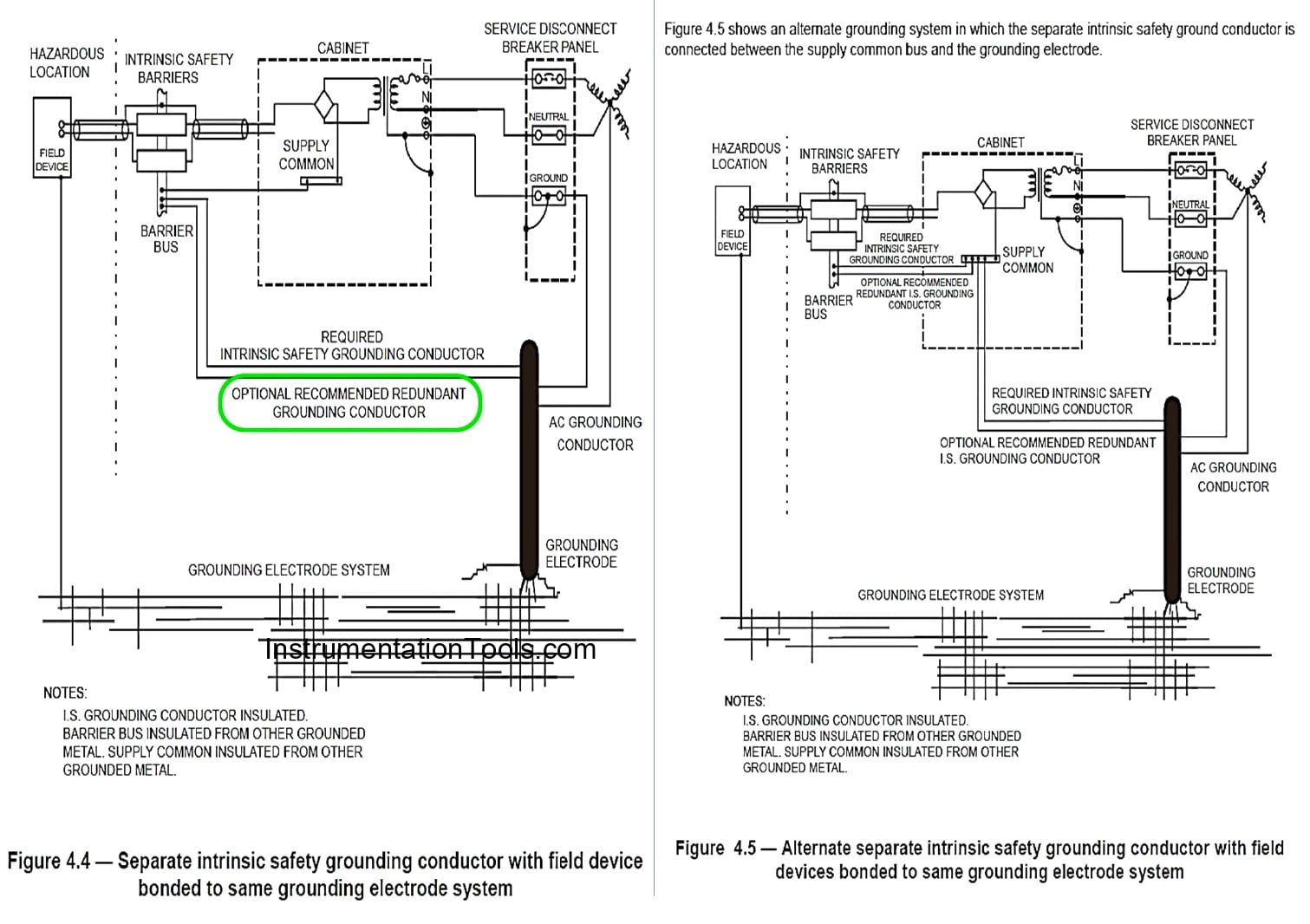
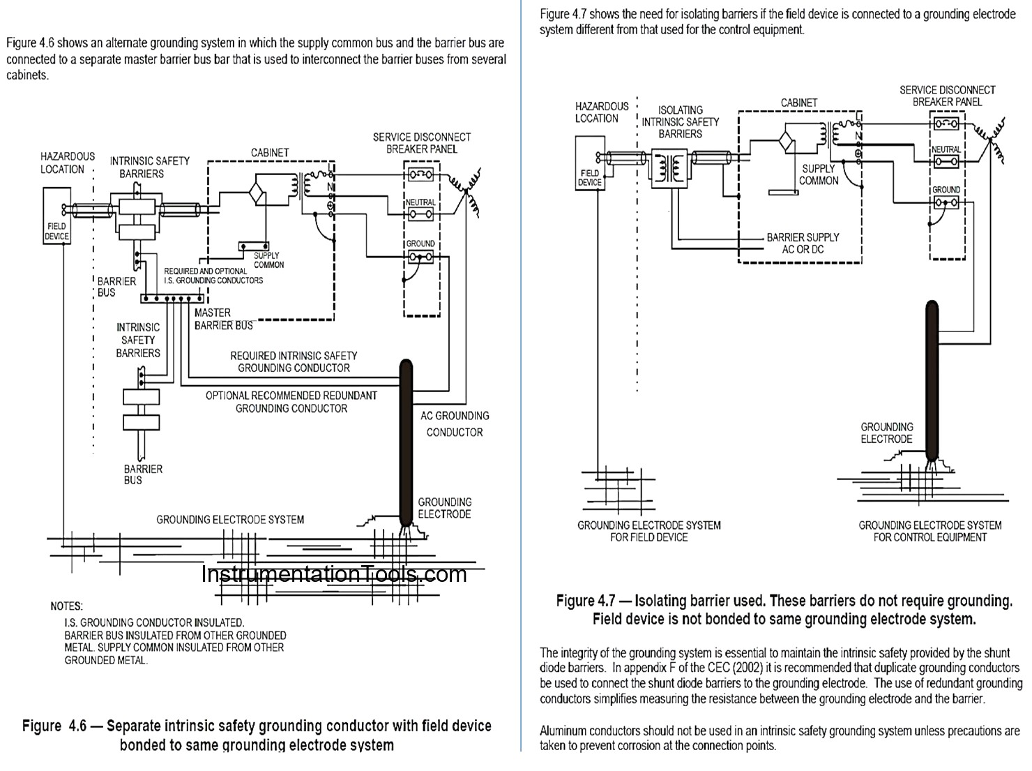
FIG-18: API Recommended Practice RP-12 for ISE (Intrinsic Safety Earth) Bar.
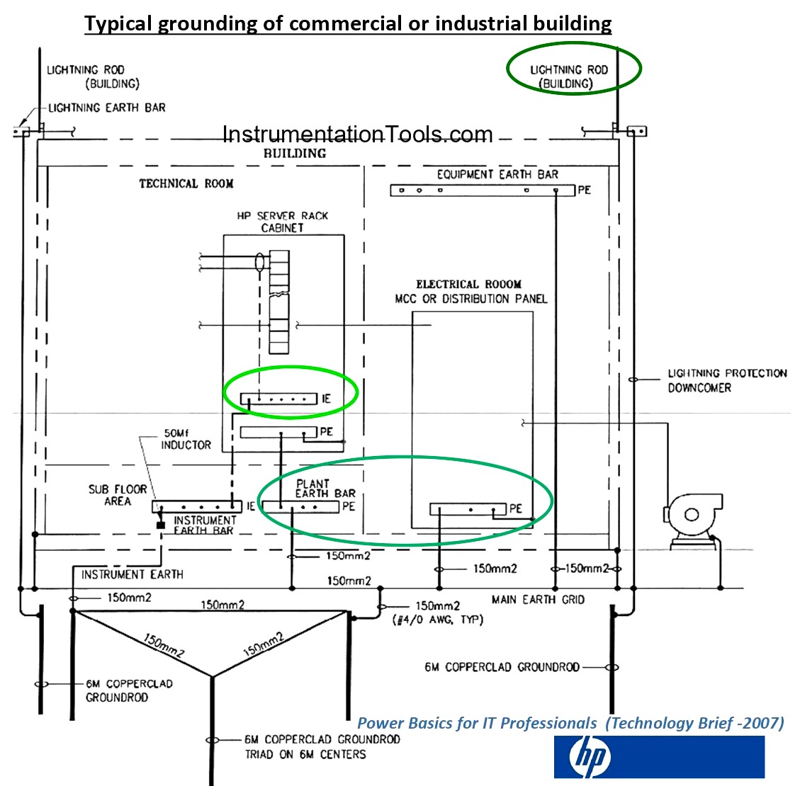
FIG-19: Earthing Requirements Configuration Model Proposed by HP.
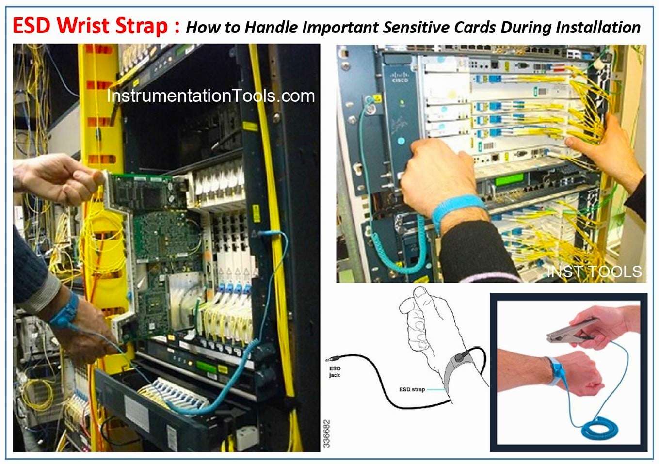
FIG-20: How to Handle Important Sensitive Cards During Installation.
References:
- Some Earthing Aspects in Industrial Process Plants
- Earthing Requirements in Process Control Industries
- Instrumentation Earthing
- Electrical MCC Signal Interface Termination