In a previous article, we talked about the PUT command and how we use it to communicate between two PLCs wither they are in the same project or in two different projects. In this article, we are going to talk about the GET command used for the Siemens PLC-to-PLC communication project for data exchange.
What is the GET command?
Just like the put command a GET command is a TIA Portal built-in function block FB that is used exclusively for S7-Family CPUs to get data from a remote partner PLC to a local PLC. Opposite to the PUT command, instead of putting data from PLC_1 into PLC_2 the GET command will get data from the PLC_2 into PLC_1.
When using GET command, I would have two PLCs, where I need to get data from one PLC called partner to another PLC called local. The Local PLC is where the GET command will be programmed.
In addition to a Profinet connection between the two PLCs. Some configurations must be done to the partner PLC, to enable it to be accessed by the other PLC.
We will create a sample project to show how to use the GET command.
Siemens PLC-to-PLC Communication Project
We will assume a sample project where we have two PLCs in the same project, PLC_1 which will act as the local PLC and PLC_2 which is the partner PLC.
To create a situation where we need to use the GET command, we will assume that we want to read/get an integer from the partner PLC_2 to the local PLC_1.
First, let’s create a new project and add the two PLCs. See picture 1.
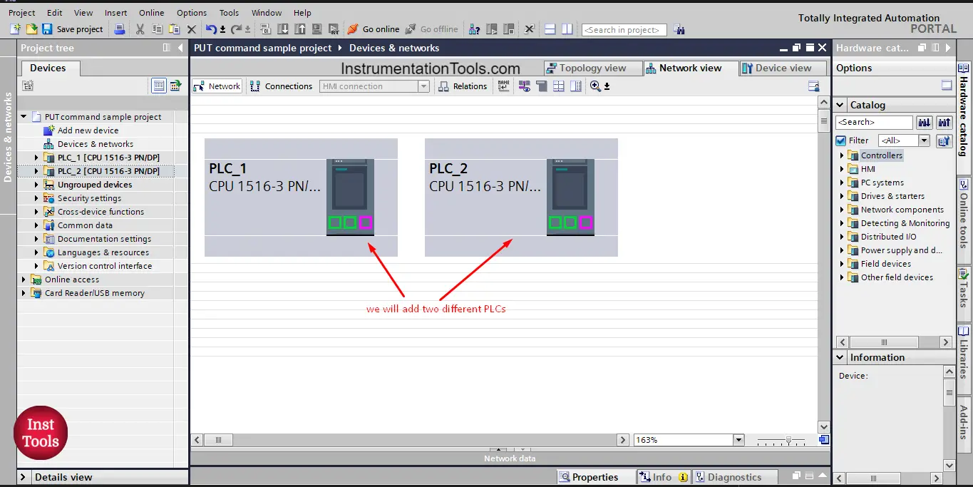
picture 1. Create a new project and add two PLCs.
Now, we need to configure the partner PLC_2 to enable the GET access from PLC_1. We also need to prepare the data that will be moved from PLC_2 into PLC_1.
First, we need to allow the access of the GET command to the PLC_2 that will give the data. See picture 2.
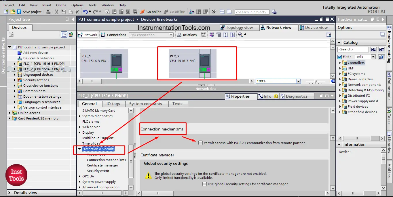
picture 2. Allow GET command access.
As you see from the picture, we allow the GET command to access the PLC_2 from the Properties of the PLC_2, in the Protection and security option, click on the
“Permit access with PUT/GET communication from remote partner”
Now, I am allowed to read/get data from the partner PLC_2 using the GET command.
NEXT, we want to create the data that will be moved to the PLC_1, we assumed that PLC_1 wants to get an integer from PLC_2.
We will define an integer tag named “ SendDataToPLC_1” this integer tag will be read from PLC_2 into PLC_1. See picture 3.
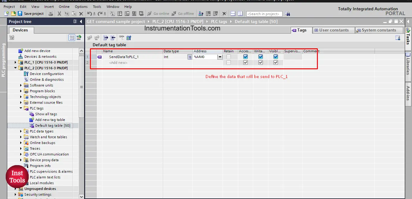
picture 3. Define data to be moved to PLC_1
And that is it; this is the entire configuration you need to prepare from the PLC_2 side to be able to receive data through the GET command.
NOW, we go to PLC_1, in PLC_1 we want to create logic where we use the GET command to read data from the PLC_2.
As we did in the last article, we will just drag and drop the GET command into our Main OB1. See picture 4.
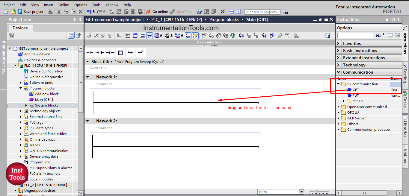
picture 4. Drag and drop the GET command
Note that, the GET command is found in the S7 communication folder, as it is an exclusive function for S7 family PLC, because it involves safety issues. Remember in picture 2 when we allowed the use of GET command it was in the Security and Protection attribute of the PLC properties as it is related to PLC safety and protection.
When you drag and drop the GET command into your, you will asked to create a data block instance as the GET command is essentially a function block FB. See picture 5.
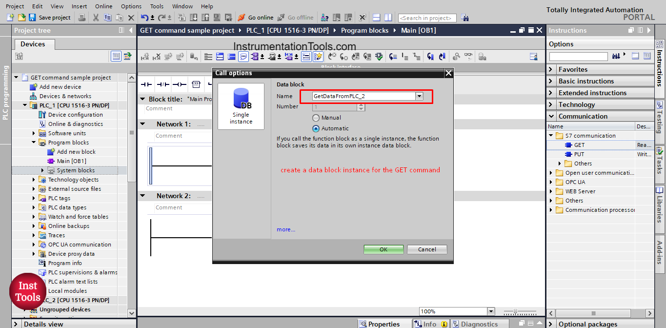
picture 5. Create a data instance for the GET command.
Now, that we added the GET command to our logic, we need to start configuring the GET block as we did before with the put command. To open the configuration views of the GET command press the small blue icon on top of the block. See picture 6.
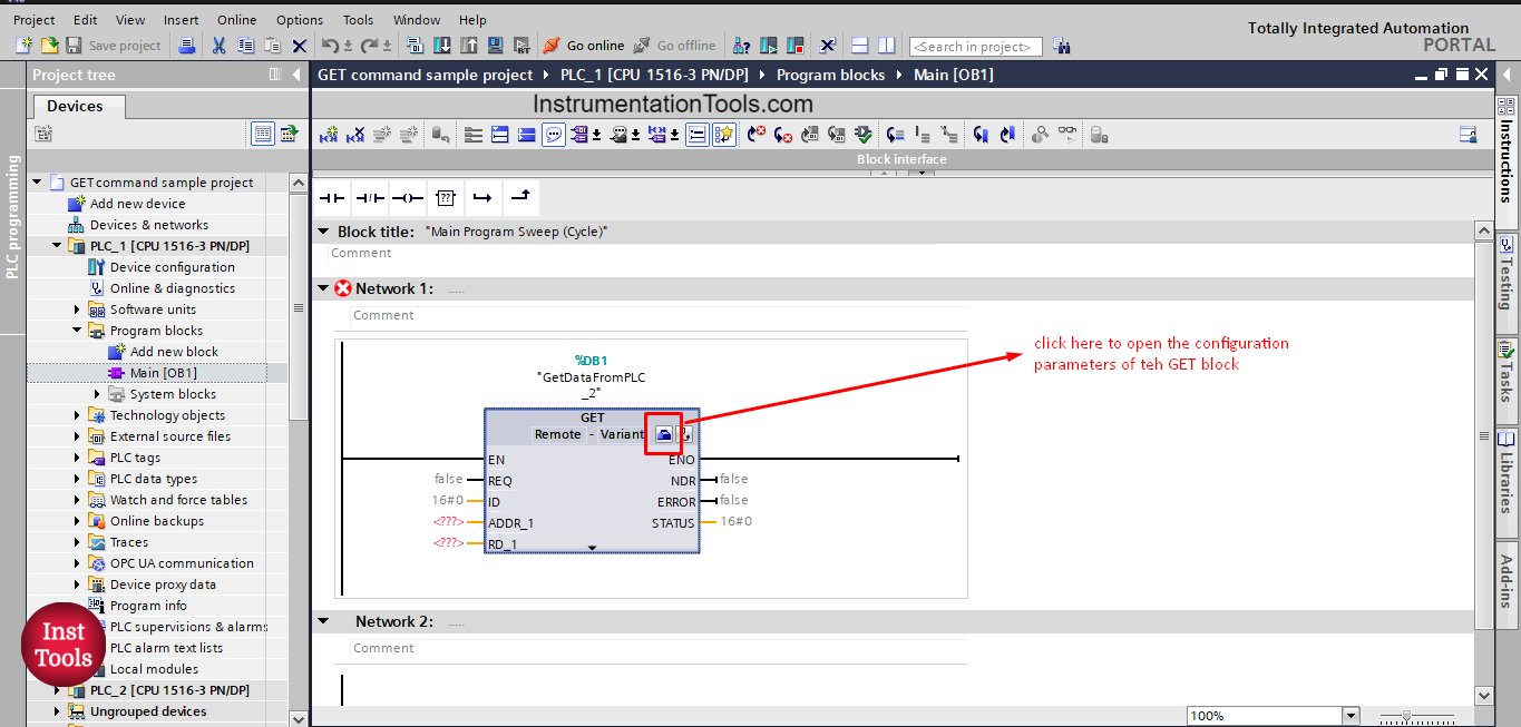
picture 6. Open configuration view.
We have two main parameters to configure, the connection parameter and the block parameter. See picture 7.
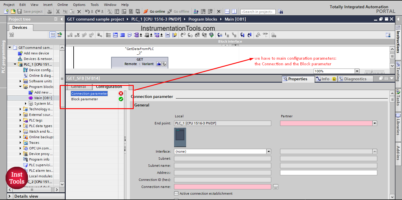
picture 7. GET block configuration.
As you can see from the picture, the Local PLC is the PLC where the GET command is called. Whereas the Partner PLC is the one that will give the data, it is also the same one which we allowed the GET access for. In our project the partner PLC is PLC_2.
You can see also from the picture that the partner is empty and we have to select the PLC. See picture 8.
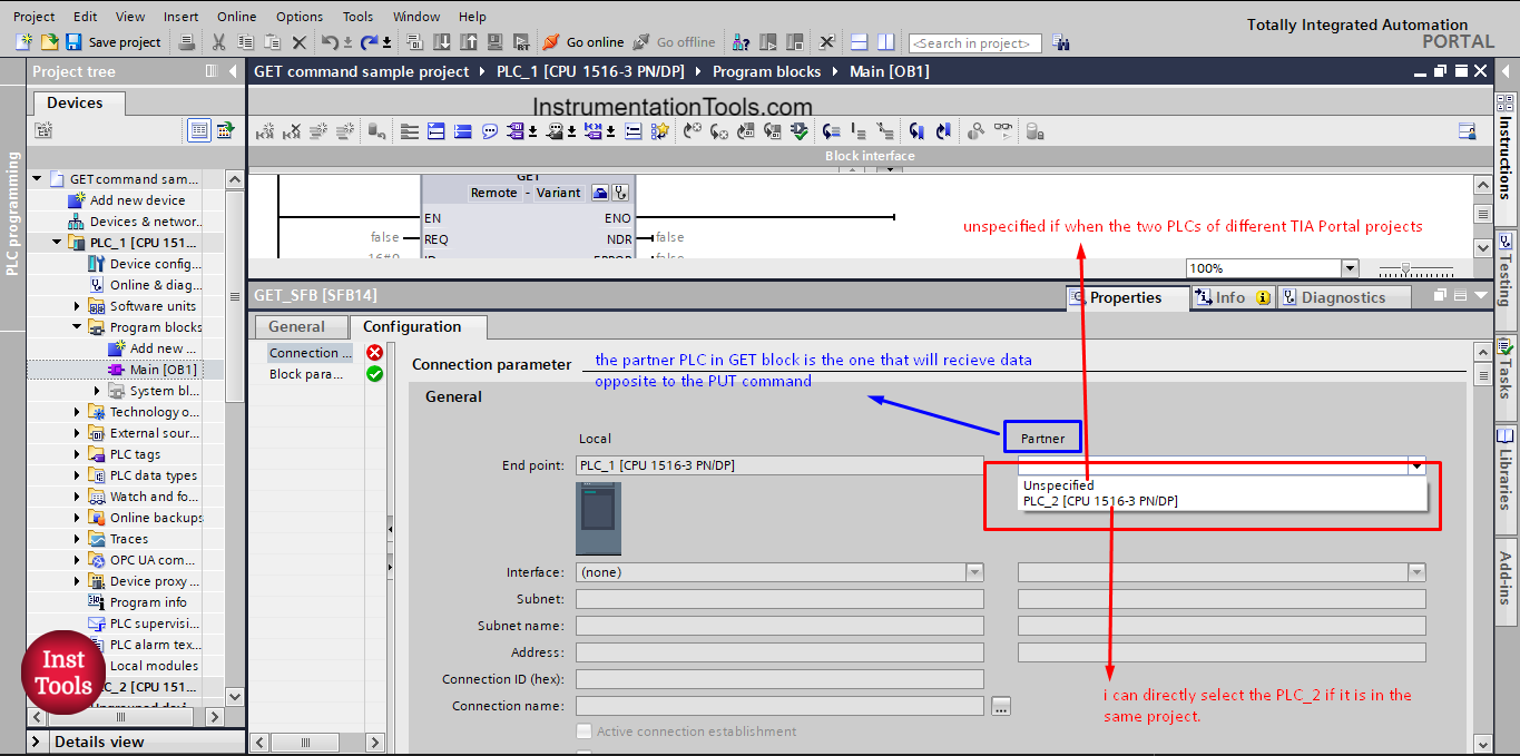
picture 8. Different option in the partner list
As you can see, we have two different options to select from for the Partner PLC.
Unspecified is when the PLCs are of different TIA Portal project and if the PLCs are of the same TIA Portal project, then you will find the other PLC in the list.
When you choose the PLC_2 option as our PLCs are in the same project, the connection configuration will be automatically filled in. See picture 9.
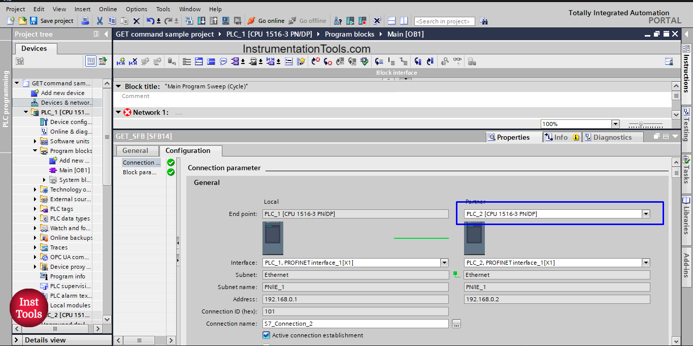
picture 9. PLC_2 as partner
Because both PLCs are in the same project, when I choose the PLC_2 option, all connection parameters will be automatically filled in.
On the other hand, if the partner PLC is from a different project, then I will choose Unspecified option, and in that case I will have to fill in some data such as the Partner PLC IP address. See picture 10.
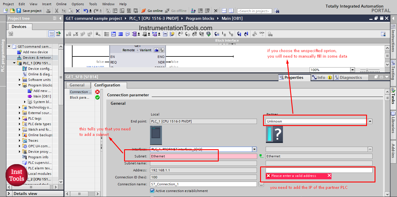
picture 10. Partner PLC as unspecified.
As you can see, when the partner is Unspecified, then you will need to manually add some information such as the partner PLC IP address.
You can also see that we need to add a subnet to the local PLC_1. To do that, you just go to the Profinet properties of the PLC_1 and select to add a new subnet. See picture 11.
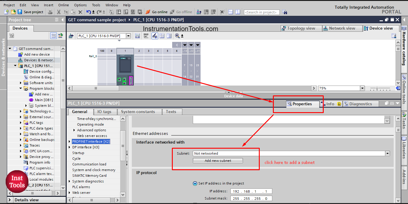
Picture 11. Add subnet for PLC_1
After adding a new Subnet to PLC_1, the connection parameter configuration will be complete. See picture 12.
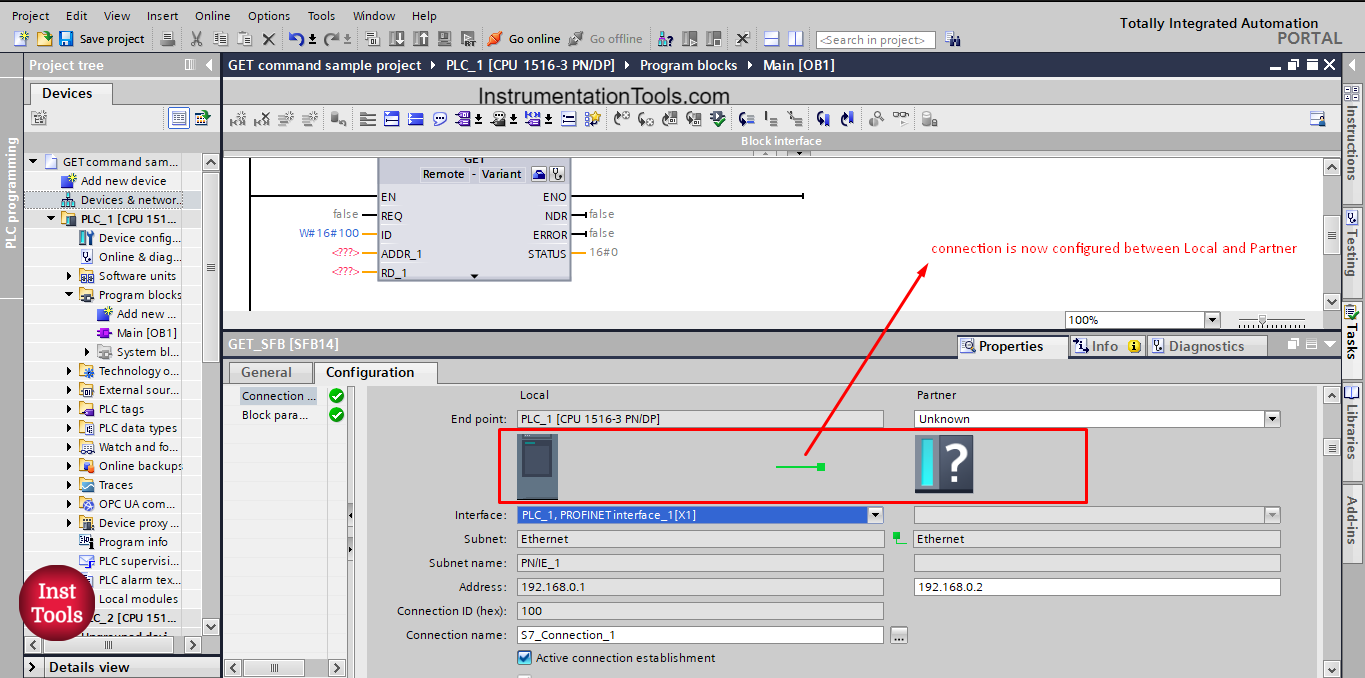
picture 12. Connection parameter is complete.
The next configuration we need to take care of is the block parameter.
In the block parameter we define the data that will be moved between the two PLCs and also the trigger signal that will allow the start of execution of the GET block. See picture 13.
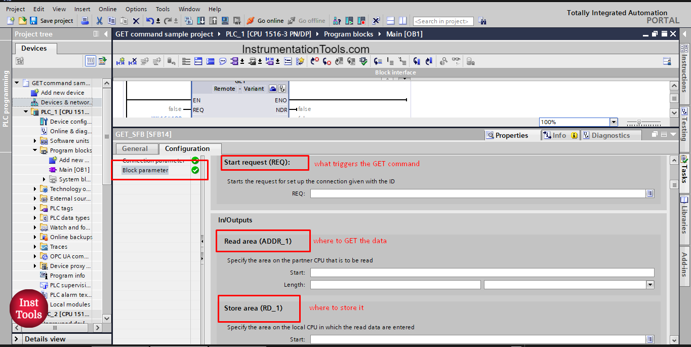
picture 13. Block parameter.
As you can see, we need to define the trigger signal for the GET block and we also need to define what data will be moved from PLC_2 (Read area ADDR_1) and where will this data go (Store area RD_1).
We already define the ADDR_1 before which is the SendDataToPLC_1 integer tag we defined inside PLC_2.
NOW, we will define the store area for that integer tag and the trigger signal. See picture 14.
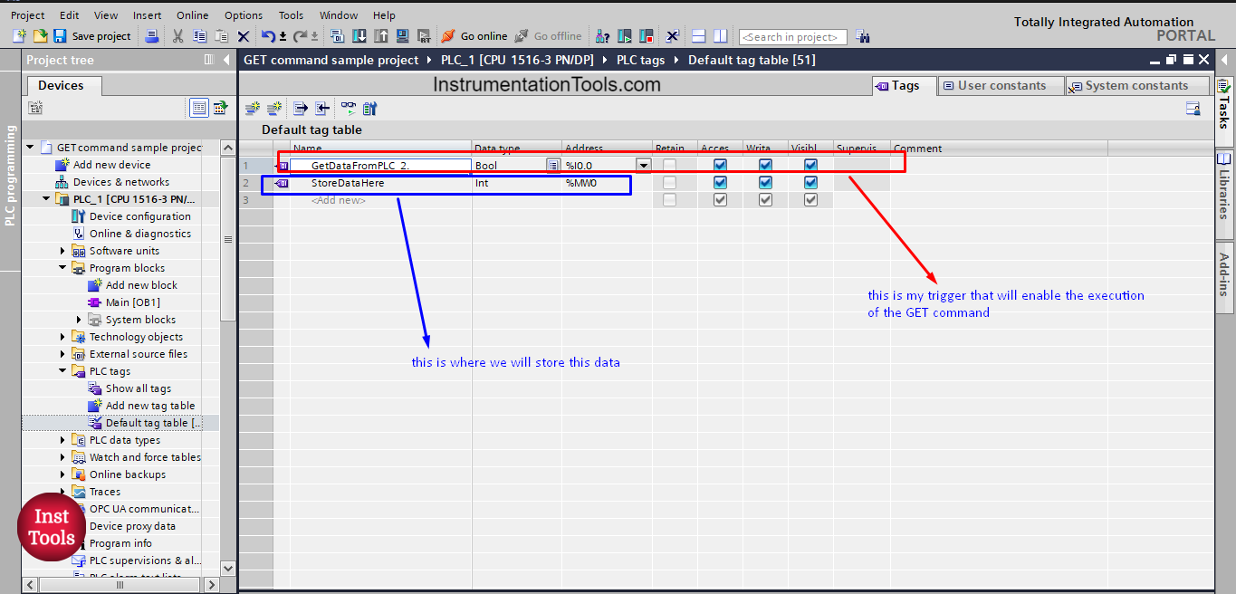
picture 14. Define trigger signal and store area
After we defined the trigger signal, ADDR_1 and the RD_1, we will fill in these parameter to the block configuration. See picture 15.
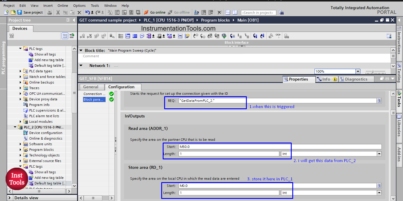
Picture 15. Fill in the block parameter
Now, the configuration of the GET block is finished and you can see that the Block is now ready to be downloaded and run. See picture 16.
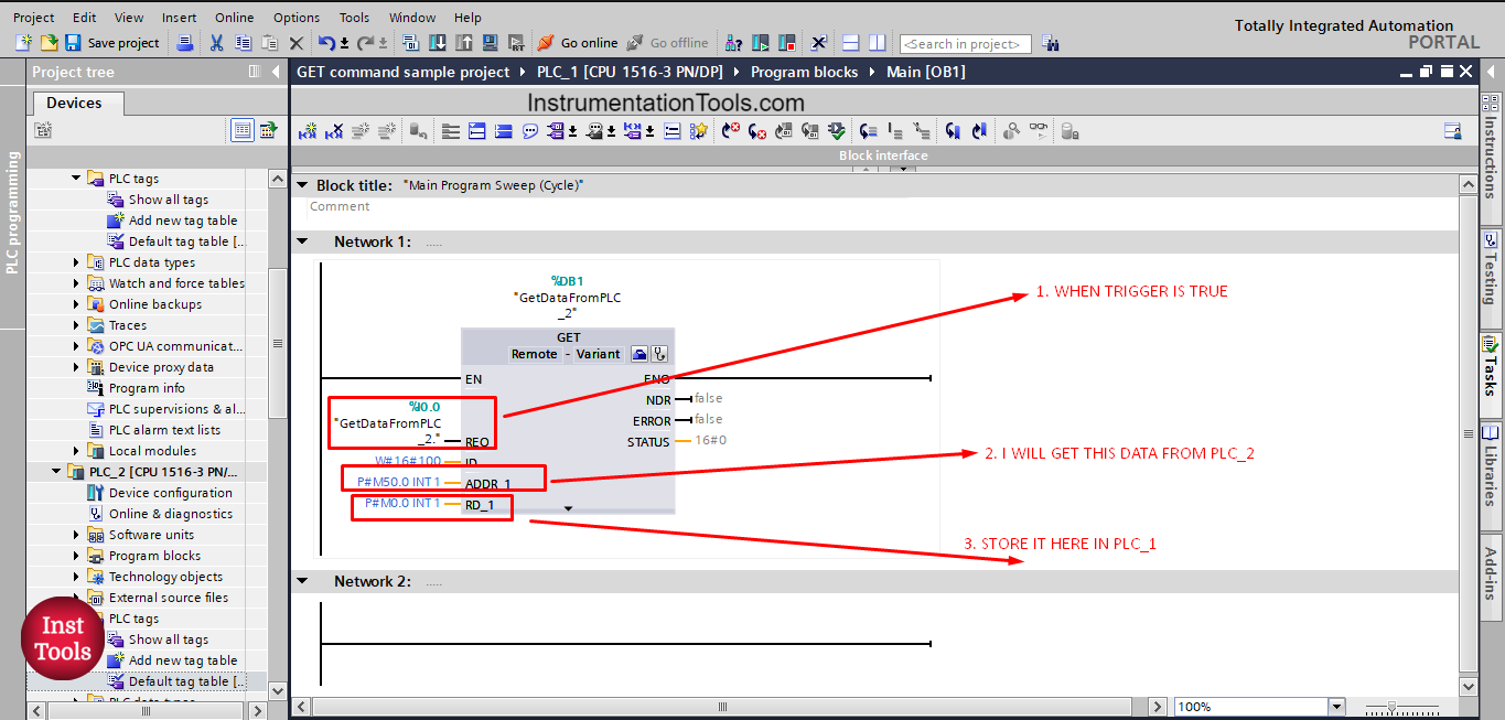
picture 16. GET block
The GET block is now configured and once the trigger signal is active the block will read the ADDR_1 from PLC_2 and write it into RD_1 in PLC_1.
In the next article, we will discuss another method of PLC-to-PLC communication.
Download the project files.
If you liked this article, then please subscribe to our YouTube Channel for Instrumentation, Electrical, PLC, and SCADA video tutorials.
You can also follow us on Facebook and Twitter to receive daily updates.
Read Next:
- Free PLC Training for Students
- Top Embedded Systems Projects
- How to Choose a PLC for a Project?
- What is Multi-touch Technology?
- MTech Project Ideas for Students


this is very important class i got and it’s helpful.