Electromagnetic Flow Meters, simply known as mag flow meter is a volumetric flow meter that is ideally used for wastewater applications and other applications that experience low-pressure drop and with appropriate liquid conductivity required.
The device doesn’t have any moving parts and cannot work with hydrocarbons and distilled water. Mag flow meters are also easy to maintain.
Electromagnetic Flow Meters

Principle of Magnetic Flow Meter Based on Faraday’s Law
Magnetic flow meters work based on Faraday’s Law of Electromagnetic Induction.
According to this principle, when a conductive medium passes through a magnetic field B, a voltage E is generated which is proportional to the velocity v of the medium, the density of the magnetic field, and the length of the conductor.

In a magnetic flow meter, a current is applied to wire coils mounted within or outside the meter body to generate a magnetic field. The liquid flowing through the pipe acts as the conductor and this induces a voltage that is proportional to the average flow velocity.
This voltage is detected by sensing electrodes mounted in the Magflow meter body and sent to a transmitter which calculates the volumetric flow rate based on the pipe dimensions.
Mathematically, we can state Faraday’s law as
E is proportional to V x B x L
[E is the voltage generated in a conductor, V is the velocity of the conductor, B is the magnetic field strength and L is the length of the conductor].
It is very important that the liquid flow that is to be measured using the magnetic flow meter must be electrically conductive.
Faraday’s Law indicates that the signal voltage (E) is dependent on the average liquid velocity (V), the length of the conductor (D), and the magnetic field strength (B). The magnetic field will thus be established in the cross-section of the tube.

Basically, when the conductive liquid flows through the magnetic field, voltage is induced. To measure this generated voltage (which is proportional to the velocity of the flowing liquid), two stainless steel electrodes are used which are mounted opposite each other.
The two electrodes which are placed inside the flow meter are then connected to an advanced electronic circuit that has the ability to process the signal. The processed signal is fed into the microprocessor that calculates the volumetric flow of the liquid.
Electromagnetic Flow Meter Formula
Electromagnetic flow meters use Faraday’s law of electromagnetic induction to make a flow measurement.
Faraday’s law states that whenever a conductor of length ‘l’ moves with a velocity ‘v’ perpendicular to a magnetic field ‘B’, an emf ‘e’ is induced in a mutually perpendicular direction which is given by
e = Blv …(eq1)
where
B = Magnetic flux density (Wb/m2)
l = length of conductor (m)
v = Velocity of the conductor (m/s)
The volume flow rate Q is given by
Q = (πd2/4) v …(eq2)
where
d = diameter of the pipe
v = average velocity of flow (conductor velocity in this case)
From equation (eq1)
v = e/Bl
Q = πd2e/4Bl
Q = Ke
where K is a meter constant.
Thus the volume flow rate is proportional to the induced emf. In Practical applications, we have to enter the meter constant ‘K’ value in the magnetic flow meter which is available in the vendor catalog/manual.
Limitations of Electromagnetic Flow Meters
(i) The substance being measured must be conductive. Therefore, it can’t be employed for metering the flow rate of gases and steam, petroleum products, and similar liquids having very low conductivity.
(ii) To render the meter insensitive to variations in the resistance of liquid, the effective resistance of the liquid between the electrodes should not exceed 1% of the impedance of the external circuit.
(iii) It is a very expensive device.
(iv) As the meter always measures the volume rate, the volume of any suspended matter in the liquid will be included.
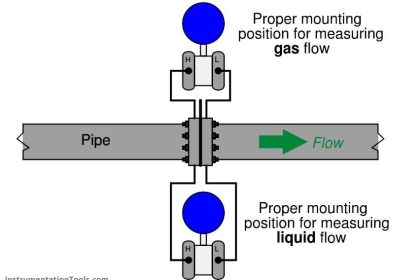
(v) To avoid any trouble that would be caused by entrained air, when the flow tube is installed in a horizontal pipeline, the electrodes should be on the horizontal diameter.
(vi) As a zero check on the installation can be performed only by stopping the flow, isolating valves are required and a bypass may also be necessary through which the flow may be directed during a zero check.
(vii) The pipe must run full, in case regulating valves are installed upstream of the meter.
Advantages of Electromagnetic Flow Meter
(i) The obstruction to the flow is almost nil and therefore this type of meter can be used for measuring heavy suspensions, including mud, sewage, and wood pulp.
ii) There is no pressure head loss in this type of flow meter other than that of the length of straight pipe that the meter occupies.
(iii) They are not very much affected by upstream flow disturbances.
(iv) They are practically unaffected by variations in density, viscosity, pressure, and temperature.
(v) Electric power requirements can be low (15 or 20 W), particularly with pulsed DC types.
(vi) These meters can be used as bidirectional meters.
(vii) The meters are suitable for most acids, bases, water, and aqueous solutions because the lining materials selected are not only good electrical insulators but also are corrosion resistant.
(viii) The meters are widely used for slurry services not only because they are obstruction-less but also because some of the liners such as polyurethane, neoprene, and rubber have good abrasion or erosion resistance.
(ix) They are capable of handling extremely low flows.
Applications of Magnetic Flow Meters
This electromagnetic flow meter being a non-intrusive type, can be used in general for any fluid which is having a reasonable electrical conductivity above 10 microsiemens/cm.
Fluids like sand water slurry, coal powder, slurry, sewage, wood pulp, chemicals, water other than distilled water in large pipelines, hot fluids, highly viscous fluids especially in food processing industries, and cryogenic fluids can be metered by the electromagnetic flow meter.
How to Use Magnetic Flow Meters?
Magnetic flowmeters measure the velocity of conductive liquids in pipes, such as water, acids, caustic, and slurries. Magnetic flowmeters can be measured properly when the electrical conductivity of the liquid is greater than approximately 5μS/cm.
Be careful because using magnetic flowmeters on fluids with low conductivity, such as deionized water, boiler feed water, or hydrocarbons, can cause the flowmeter to turn off and measure zero flow.
This flowmeter does not obstruct flow, so it can be applied to clean, sanitary, dirty, corrosive, and abrasive liquids. Magnetic flowmeters can be applied to the flow of liquids that are conductive, so hydrocarbons and gases cannot be measured with this technology due to their non-conductive nature and gaseous state, respectively.
Magnetic flowmeters do not require much upstream and downstream straight run so they can be installed in relatively short meter runs. Magnetic flowmeters typically require 3-5 diameters of upstream straight run and 0-3 diameters of downstream straight run measured from the plane of the magnetic flowmeter electrodes.
Applications for dirty liquids are found in water, wastewater, mining, mineral processing, power, pulp and paper, and chemical industries. Water and wastewater applications include custody transfer of liquids in force mains between water/wastewater districts.
Magnetic flowmeters are used in water treatment plants to measure treated and untreated sewage, process water, water, and chemicals. Mining and mineral process industry applications include process water process slurry flows and heavy media flows.
With proper attention to the materials of construction, the flow of highly corrosive liquids (such as acid and caustic) and abrasive slurries can be measured. Corrosive liquid applications are commonly found in the chemical industry processes, and in chemical feed systems used in most industries. Slurry applications are commonly found in the mining, mineral processing, pulp and paper, and wastewater industries.
Magnetic flowmeters are often used where the liquid is fed using gravity. Be sure that the orientation of the flowmeter is such that the flowmeter is completely filled with liquid. Failure to ensure that the flowmeter is completely filled with liquid can significantly affect the flow measurement.
Be especially careful when operating magnetic flowmeters in vacuum service because some magnetic flowmeter liners can collapse and be sucked into the pipeline in vacuum service, catastrophically damaging the flowmeter.
Note that vacuum conditions can occur in pipes that seemingly are not exposed to vacuum service such as pipes in which a gas can condense (often under abnormal conditions).
Similarly, excessive temperature in magnetic flowmeters (even briefly under abnormal conditions) can result in permanent flowmeter damage.
If you liked this article, then please subscribe to our YouTube Channel for Instrumentation, Electrical, PLC, and SCADA video tutorials.
You can also follow us on Facebook and Twitter to receive daily updates.
Read Next:
- Flow Measurement Questions
- Impeller Flow Sensor Animation
- Rotary Flow Meter Principle
- Area Velocity Flow Meter Principle
- Why the Turndown Ratio is Important


How to check the sensor working or not??
How to check the flowrate right or wrong
electromagnetic flow meter amplifier circuit diagrams
nice
Could we detect the depth of underground waterfow path applying same principle.
Who wrote this article and date it was written on ?
how to select flow meter in RO Application
It’s a very helpful guide
nice information, very helpful
Can the mag flow meter give accurate readings if the conductivity of the medium fluctuates,
NO, it must be within the meter specifications. check flow meter datasheet