In this example program, you will learn the electrical ladder diagram control using timers and toggle switches.
Note: The ladder diagram example is prepared to understand the basic programming for electrical engineers.
Electrical Ladder Diagram Control
Problem Statement:
Design a PLC ladder logic for the following application.
We are using one toggle switch to control three motors.
When switch 1 is turned ON,
After 5 seconds, Motor 1 will be ON
After 10 seconds, Motor 2 will be ON
After 15 seconds, Motor 3 will be ON
After 20 seconds, all the motors will be OFF.
Pro PLC Learning
Our PLC learning videos help engineering graduates understand these programs from the basics.

Inputs
The inputs are listed below.
Switch 1: I0.0
Outputs
The outputs are listed below.
Motor 1: Q0.0
Motor 2: Q0.0
Motor 3: Q0.0
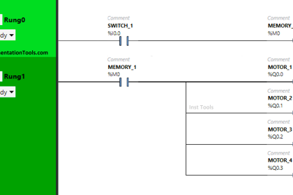
Ladder Diagram using Timers Example
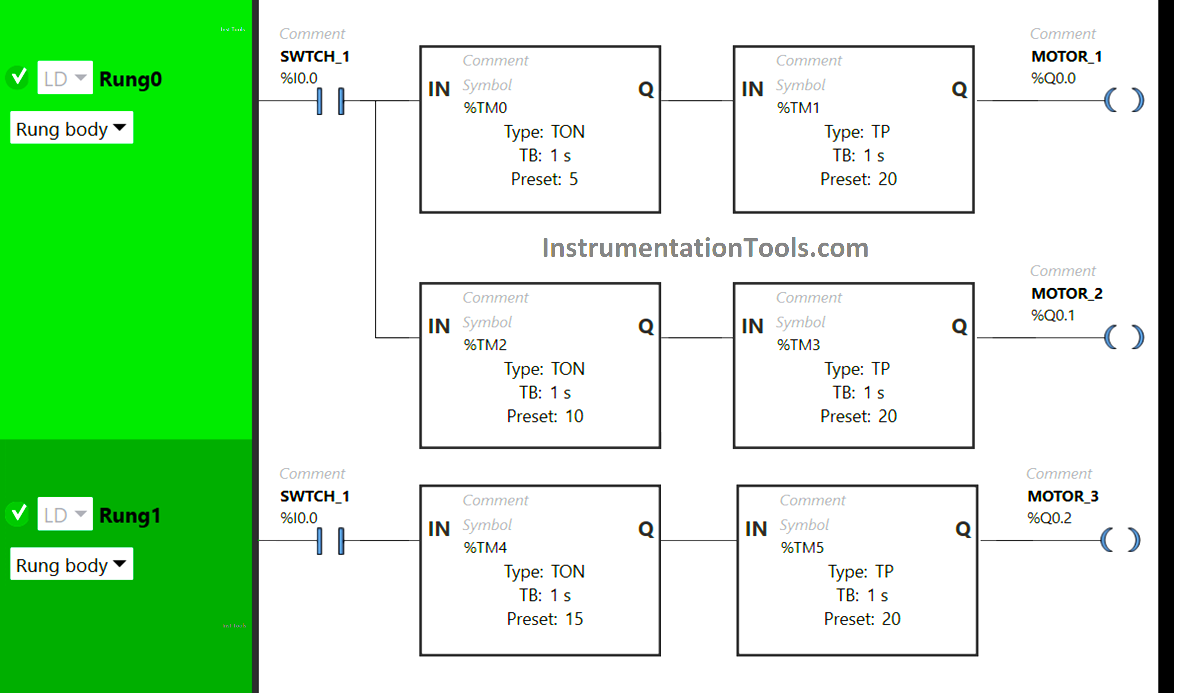
Program Description
In the PLC program, we have used Normally Open Contact for Switch 1
Two Timer Function Blocks Type TON and TP are used for Motor 1, Motor 2, and Motor 3.
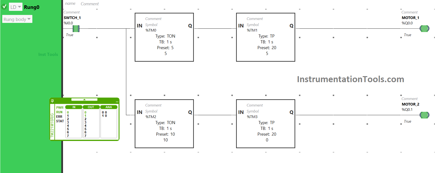
In Rung0:
Normally Open Contact is used for Switch 1.
Timer Function Block type TON is used for Motor 1 to turn it ON after a delay of 5 seconds.
Timer Function Block type TON is also used for Motor 2 to turn it ON after 10 seconds.
Timer Function Block type TP is used to keep Motor 1 ON for 20 seconds.
Timer Function Block type TP is also used for Motor 2 to keep it ON for 20 seconds.
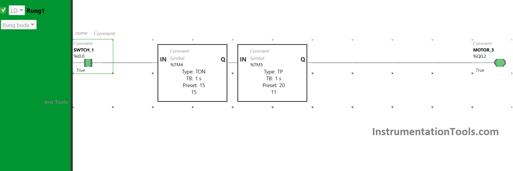
In Rung1:
1) Normally Open Contact is used for Switch 1.
2) Timer Function Block type TON is used for Motor 3 to turn it ON after a delay of 15 seconds.
3) Timer Function Block type TP is also used for Motor 3 to keep it ON for 20 seconds.
PLC Program Analysis
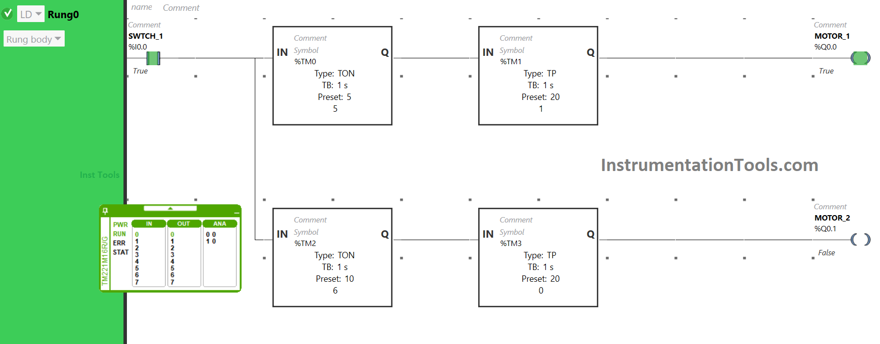
When Switch 1 is turned ON, the Timer functional block type TON (TM0) will allow the signal to flow after a delay of 5 seconds.
After 5 seconds, the signal will flow and the Timer functional block type TP (TM1) will allow the signal to flow for 20 seconds only, and in that duration of time, Motor 1 will be ON.
After 20 seconds, the signal will not flow. As a result, Motor 1 will turn OFF.
When Switch 1 is turned ON, after a delay of 10 seconds the Timer functional block type TON (TM2) will allow the signal to flow.
The Timer functional block type TP (TM3) will allow the signal to flow after 10 seconds for 20 seconds only and Motor 2 will be ON for that duration of time only. The signal will not flow after 20 seconds, t. As a result, Motor 2 will turn OFF.
When Switch 1 is turned ON, the Timer Functional Block type TON (TM4) will make it wait for 15 seconds and after that, it will allow the signal to flow.
Then, another Timer Functional Block type TP (TM5) will allow signal only for 20 seconds and Motor 3 will be ON only for that duration of time.
After that, the signal will be blocked and Motor 3 will turn OFF.
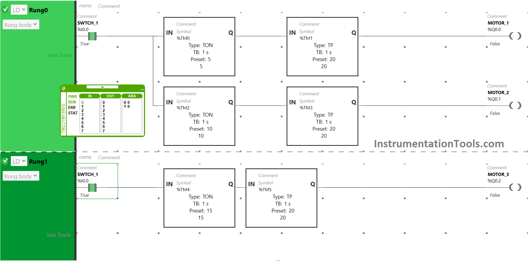
So, When Switch 1 is turned ON, Motor 1 will turn ON after 5 seconds and for 20 seconds, Motor 2 will turn ON after 10 seconds and for 20 seconds and Motor 3 will turn ON after 15 seconds and for 20 seconds.
If you liked this article, please subscribe to our YouTube Channel for PLC and SCADA video tutorials.
You can also follow us on Facebook and Twitter to receive daily updates.
Read Next:
- From Boolean Algebra to PLC Logic
- PLC Program for Solenoid & Pilot Lamp
- PLC Programming Example with Motor
- PLC to Start or Stop using 1 Switch Program
- PLC Code to Start & Stop Motor and Pump