Inst ToolsInst ToolsInst Tools
  • Courses
  • Automation
    • PLC
    • Control System
    • Safety System
    • Communication
    • Fire & Gas System
  • Instrumentation
    • Design
    • Pressure
    • Temperature
    • Flow
    • Level
    • Vibration
    • Analyzer
    • Control Valve
    • Switch
    • Calibration
    • Erection & Commissioning
  • Interview
    • Instrumentation
    • Electrical
    • Electronics
    • Practical
  • Q&A
    • Instrumentation
    • Control System
    • Electrical
    • Electronics
    • Analog Electronics
    • Digital Electronics
    • Power Electronics
    • Microprocessor
  • Request
Search
  • Books
  • Software
  • Projects
  • Process
  • Tools
  • Basics
  • Formula
  • Power Plant
  • Root Cause Analysis
  • Electrical Basics
  • Animation
  • Standards
  • 4-20 mA Course
  • Siemens PLC Course
Reading: Capacitive Tank Gauges
Share
Font ResizerAa
Inst ToolsInst Tools
Font ResizerAa
  • Courses
  • Design
  • PLC
  • Interview
  • Control System
Search
  • Courses
  • Automation
    • PLC
    • Control System
    • Safety System
    • Communication
    • Fire & Gas System
  • Instrumentation
    • Design
    • Pressure
    • Temperature
    • Flow
    • Level
    • Vibration
    • Analyzer
    • Control Valve
    • Switch
    • Calibration
    • Erection & Commissioning
  • Interview
    • Instrumentation
    • Electrical
    • Electronics
    • Practical
  • Q&A
    • Instrumentation
    • Control System
    • Electrical
    • Electronics
    • Analog Electronics
    • Digital Electronics
    • Power Electronics
    • Microprocessor
  • Request
Follow US
All rights reserved. Reproduction in whole or in part without written permission is prohibited.
Inst Tools > Blog > Level Measurement > Capacitive Tank Gauges

Capacitive Tank Gauges

Last updated: December 15, 2019 4:40 pm
Editorial Staff
Level Measurement
No Comments
Share
1 Min Read
SHARE

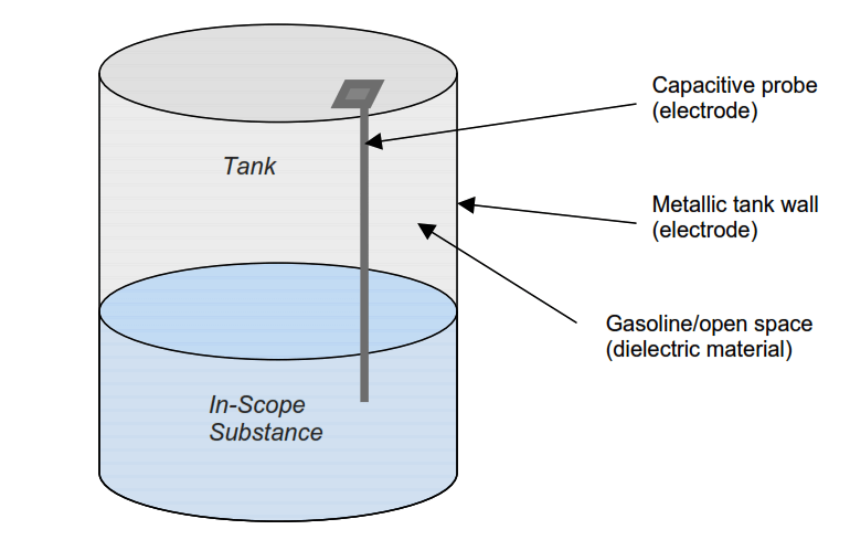
In capacitive tank gauges, the principle of capacitor is used for level measurement.

A constant voltage is applied to a metallic probe within the tank. The corresponding current is then monitored. This current is proportional to the capacitance from the metallic probe to a second electrode. The second electrode is generally a wall of the tank.

Capacitor Interpretation

Figure: A capacitor interpretation of the elements of a capacitive level measurement system

False high-level indications are a typical failure mode of this type of system. This kind of failure can be caused by one of the capacitive plates becoming coated with a material, such as the product being stored, to such an extent that the sensing element becomes connected to the ground.

Capacitive Tank Gauges
Capacitive Tank Gauges

Figure: Simple diagram to demonstrate a capacitance-based level measurement system

Apart from the issue of plate coating, the capacitive level measurement system experiences very little operational degradation. This is because there are no moving parts.

Read Next:

  • Capacitive Level Measurement
  • Tank Level Detection Switches
  • Capacitance Level Sensor
  • Animation of Capacitance Sensors
  • Calibration of Capacitance Level Sensor
Don't Miss Our Updates
Be the first to get exclusive content straight to your email.
We promise not to spam you. You can unsubscribe at any time.
Invalid email address
You've successfully subscribed !

Continue Reading

Advantages & Disadvantages of Level Measurement Systems
Servo Operated Float Level Measurement
Laser Level Measurement Principle
DP Level Transmitter Auto Calibration
Float Level Measurement
Level Measurement with Dry leg and Installed Below Tapping Point
Share This Article
Facebook Whatsapp Whatsapp LinkedIn Copy Link
Share
Leave a Comment

Leave a Reply Cancel reply

Your email address will not be published. Required fields are marked *

Stay Connected

128.3kFollowersLike
69.1kFollowersFollow
210kSubscribersSubscribe
38kFollowersFollow

Categories

Explore More

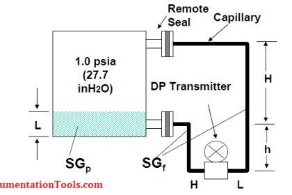
Closed Tank Remote Seal Capillary type DP Transmitter
Optical Level Switch Working Principle
How a Level Switch Works
Conductive Level Switch Principle
Boiler Drum Level Transmitter Calibration
Cat and Mouse type Level Indicator
Manual Level Measurement
Bubbler Level Sensor

Keep Learning

Level Transmitter Design

Level Transmitter and Level Gauge Design Tips

Level Calculation with Remote Seals

Level Calculation with Remote Seals

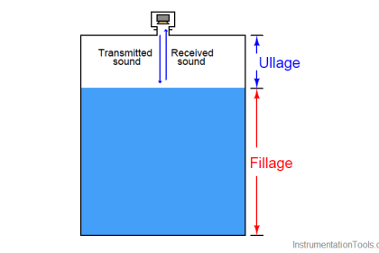
Ultrasonic level measurement

Ultrasonic Level Measurement

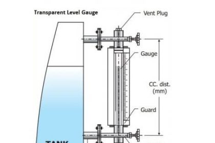
Transparent Level Gauge

Level Indicators Working Principle

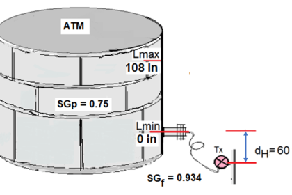
Remote Capillary Level Transmitter Mounted below the Zero Level

How to Calculate mmWC Range of Level Transmitter with Examples?

Radar Level Transmitter in Briddle level Measurement

Radar Level Transmitter in Briddle level Measurement

Bubbler level measurement

what is a Bubbler System?

Level Gauge Theory

Types of Level Gauges

Learn More

OMRON PLC program for waste-burning automation

Waste-Burning System OMRON PLC Program Example

pH Monitoring System Triggers an Alarm

pH Monitoring System Triggers an Alarm

Digital Instrument Example

Digital Measuring Instruments – Types, Functions, Advantages, Disadvantages

orifice-plate

Orifice Plate Turndown ratio

Static VI Characteristics of Thyristor

Thyristors – Working, VI Characteristics, Turn ON Methods

Instrumentation Engineering Materials Test

Instrumentation Materials Test

Select Right Type of Controller

How to Select the Right Type of Controller

What is Rapid Spanning Tree Protocol

What is Rapid Spanning Tree Protocol? – RSTP Network

Menu

  • About
  • Privacy Policy
  • Copyright

Quick Links

  • Learn PLC
  • Helping Hand
  • Part Time Job

YouTube Subscribe

Follow US
All rights reserved. Reproduction in whole or in part without written permission is prohibited.
Welcome Back!

Sign in to your account

Username or Email Address
Password

Lost your password?