Displacer level instruments exploit Archimedes’ Principle to detect liquid level by continuously measuring the weight of an object (called the displacer ) immersed in the process liquid. As liquid level increases, the displacer experiences a greater buoyant force, making it appear lighter to the sensing instrument, which interprets the loss of weight as an increase in level and transmits a proportional output signal.
In practice a displacer level instrument usually takes the following form. Process piping in and out of the vessel has been omitted for simplicity – only the vessel and its displacer level instrument are shown:
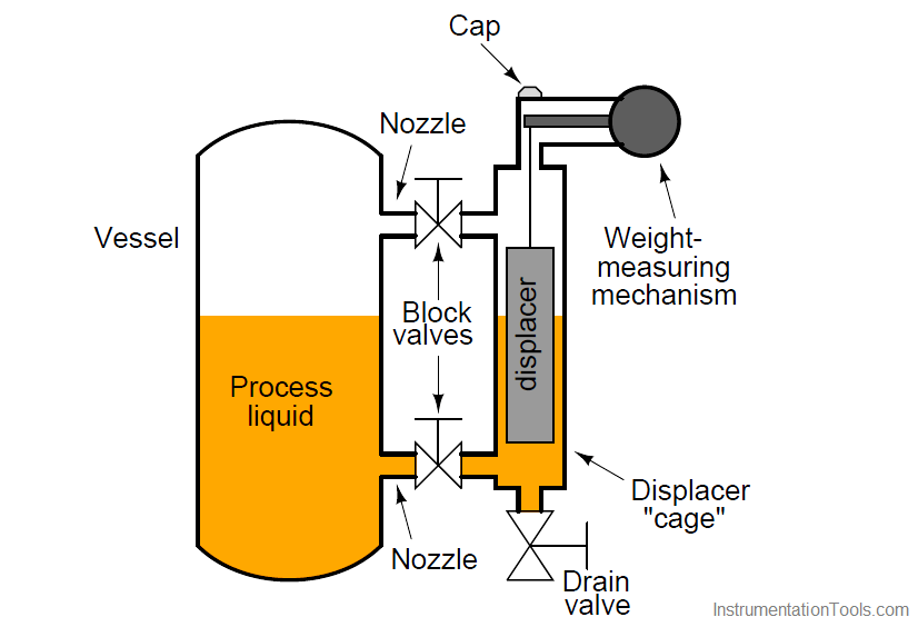
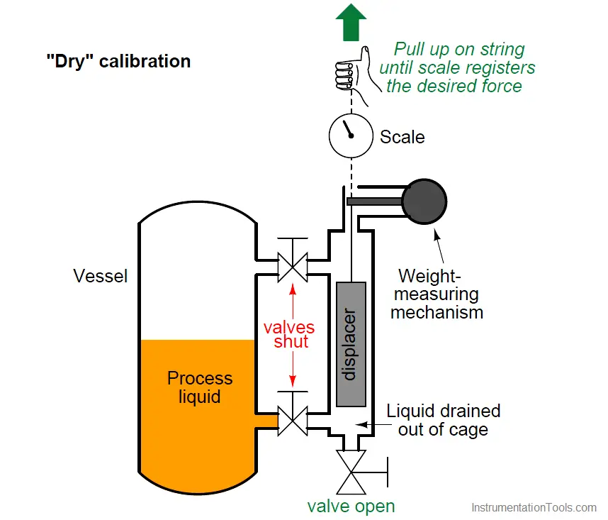
The displacer itself is usually a sealed metal tube, weighted sufficiently so it cannot float in the process liquid. It hangs within a pipe called a “cage” connected to the process vessel through two block valves and nozzles. These two pipe connections ensure the liquid level inside the cage matches the liquid level inside the process vessel, much like a sightglass.
If liquid level inside the process vessel rises, the liquid level inside the cage rises to match. This will submerge more of the displacer’s volume, causing a buoyant force to be exerted upward on the displacer. Remember that that displacer is too heavy to float, so it does not “bob” on the surface of the liquid nor does it rise the same amount as the liquid’s level – rather, it hangs in place inside the cage, becoming “lighter” as the buoyant force increases. The weight-sensing mechanism detects this buoyant force when it perceives the displacer becoming lighter, interpreting the decreased (apparent) weight as an increase in liquid level. The displacer’s apparent weight reaches a minimum when it is fully submerged, when the process liquid has reached the 100% point inside the cage.
It should be noted that static pressure inside the vessel will have negligible effect on a displacer instrument’s accuracy. The only factor that matters is the density of the process fluid, since buoyant force is directly proportional to fluid density (F = γV ).
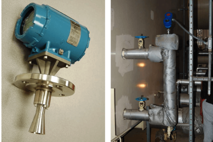
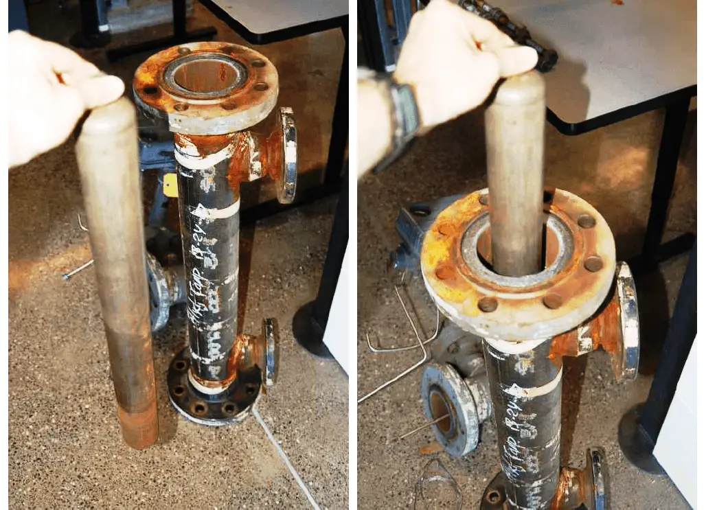
Two photos of a disassembled Level-Trol displacer instrument appear here, showing how the displacer fits inside the cage pipe:
The cage pipe is coupled to the process vessel through two block valves, allowing isolation from the process. A drain valve allows the cage to be emptied of process liquid for instrument service and zero calibration.
Some displacer-type level sensors do not use a cage, but rather hang the displacer element directly in the process vessel. These are called “cageless” sensors. Cageless instruments are of course simpler than cage-style instruments, but they cannot be serviced without de-pressurizing (and perhaps even emptying) the process vessel in which they reside. They are also susceptible to measurement errors and “noise” if the liquid inside the vessel is agitated, either by high flow velocities in and out of the vessel, or by the action of motor-turned impellers installed in the vessel to provide thorough mixing of the process liquid(s).
Full-range calibration may be performed by flooding the cage with process liquid (a wet calibration), or by suspending the displacer with a string and precise scale (a dry calibration), pulling upward on the displacer at just the right amount to simulate buoyancy at 100% liquid level:
Calculation of this buoyant force is a simple matter. According to Archimedes’ Principle, buoyant force is always equal to the weight of the fluid volume displaced. In the case of a displacer-based level instrument at full range, this usually means the entire volume of the displacer element is submerged in the liquid. Simply calculate the volume of the displacer (if it is a cylinder, V = πr2l, where r is the cylinder radius and l is the cylinder length) and multiply that volume by the weight density (γ):
Fbuoyant = γV
Fbuoyant = γπr2l
For example, if the weight density of the process fluid is 57.3 pounds per cubic foot and the displacer is a cylinder measuring 3 inches in diameter and 24 inches in length, the necessary force to simulate a condition of buoyancy at full level may be calculated as follows:
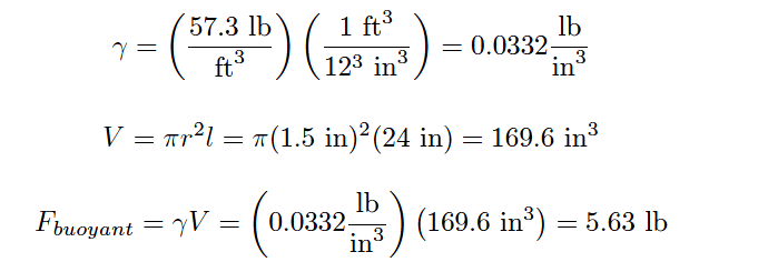
Note how important it is to maintain consistency of units! The liquid density was given in units of pounds per cubic foot and the displacer dimensions in inches, which would have caused serious problems without a conversion between feet and inches. In my example work, I opted to convert density into units of pounds per cubic inch, but I could have just as easily converted the displacer dimensions into feet to arrive at a displacer volume in units of cubic feet.
In a “wet” calibration, the 5.63 pound buoyant force will be created by the liquid itself, the technician ensuring there is enough liquid inside the cage to simulate a 100% level condition. In a “dry” calibration, the buoyant force will be simulated by tension applied upward on the displacer with a hand scale and string, the technician pulling with an upward force of 5.63 pounds to make the instrument “think” it is sensing 100% liquid level when in fact the displacer is completely dry, hanging in air.
Credits : Tony R. Kuphaldt – Creative Commons Attribution 4.0 License