Siemens Pressure transmitters / differential pressure Transmitters, for flange type (Without remote seal)
The Transmitter Lower Range Value (LRV) and Upper Range Value (URV) calculations for a siemens pressure/differential pressure transmitters.
Contents
The following figures showing calculation formulae for different measurements like level, separation (interface), and density measurements for both Open & Closed Tanks using Flange Type Pressure/Differential Pressure Transmitters.
In below figures : PMA & PME are nothing but LRV & URV of a transmitter.
LRV & URV Calculations for open containers / Open Tank


Notes
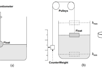
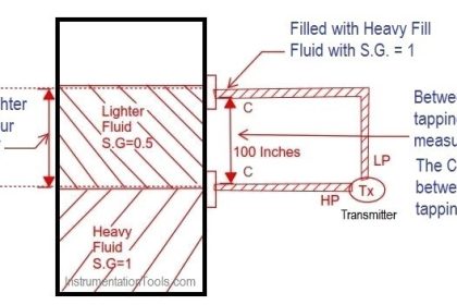
- For the separation layer (interface level) measurement, the separation layer has to be positioned between the two spigots. Also you must make sure that the level in the container is always above the top spigot.
- When measuring density, make sure that the level of the medium remains constant. The level should be above the top spigot
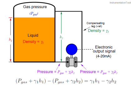
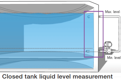
LRV & URV Calculations for closed containers / Closed Tanks


Reference : Siemens manual
Articles You May Like :
Calculate mA from PV, LRV, URV
Linear % to Square root % conversion
Closed Tank Level Calculations


great effort thanks