In the detailed design/ Engineering phase of each Process Plant Project, one of the main activities of the instrumentation and control (I&C) Team is related to designing the Process Control & Safety Systems and accordingly providing the required documentation for purchasing, supplying, and installing such systems (at the project site). In this article, we try to be familiar with the sequence of design and supply of the Process Control & Safety Systems.
Overview Sequence
The overview sequence of Design & Supplying the Process Control & Safety Systems is shown in Figure 1. As Figure 1 shows, at the first step, the I&C Team shall review all available project inputs in order to investigate and develop the Process Control Systems Philosophy, which is the core basis of their following activities and documentation for coordination with other departments/ disciplines and doing their other responsible jobs.
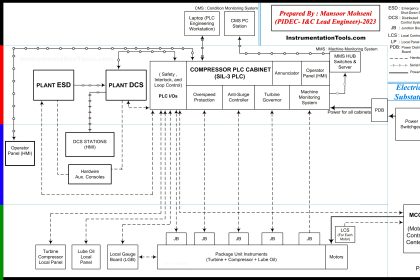
The main output document of Process Control Systems Philosophy is “System(s) Architecture Diagram” which clarifies the arrangement of required systems and their interfacings in the project plant. Accordingly, the I&C-Team shall provide other required Documents and Data for the following actions, especially for purchasing Systems, Instruments, Packages, Devices and all required Bulk Materials (Junction Boxes, Cables, Trays & Ladders, Cable Glands, Tubes & Tube Fittings …). Details of such activities and documentation, further to the role of System Architecture Document and also how to develop the Process Control Systems Philosophy can be reviewed in more detail – Check Here.
Different Systems of Project Plant
While developing the Project Control Systems Philosophy, the I&C-Team shall identify all possible systems inside the Process Plant Project and their required specifications and interfacings.
For reviewing such activities and documentation let us define some applicable abbreviations:
DCS:
Distributed/ Digital Control System is the Basic Process Control System (BPCS) which is normally used in Process Plant Projects.
ESD:
Emergency Shut Down System is the Safety Instrumented System (SIS) which is normally used in Process Plant Projects.
FGS:
Fire and Gas System is one of the plant protection systems for monitoring fire and gases (Flammable, Explosive, and Toxic) with making suitable warnings & alarms, and probably automatic reactions.
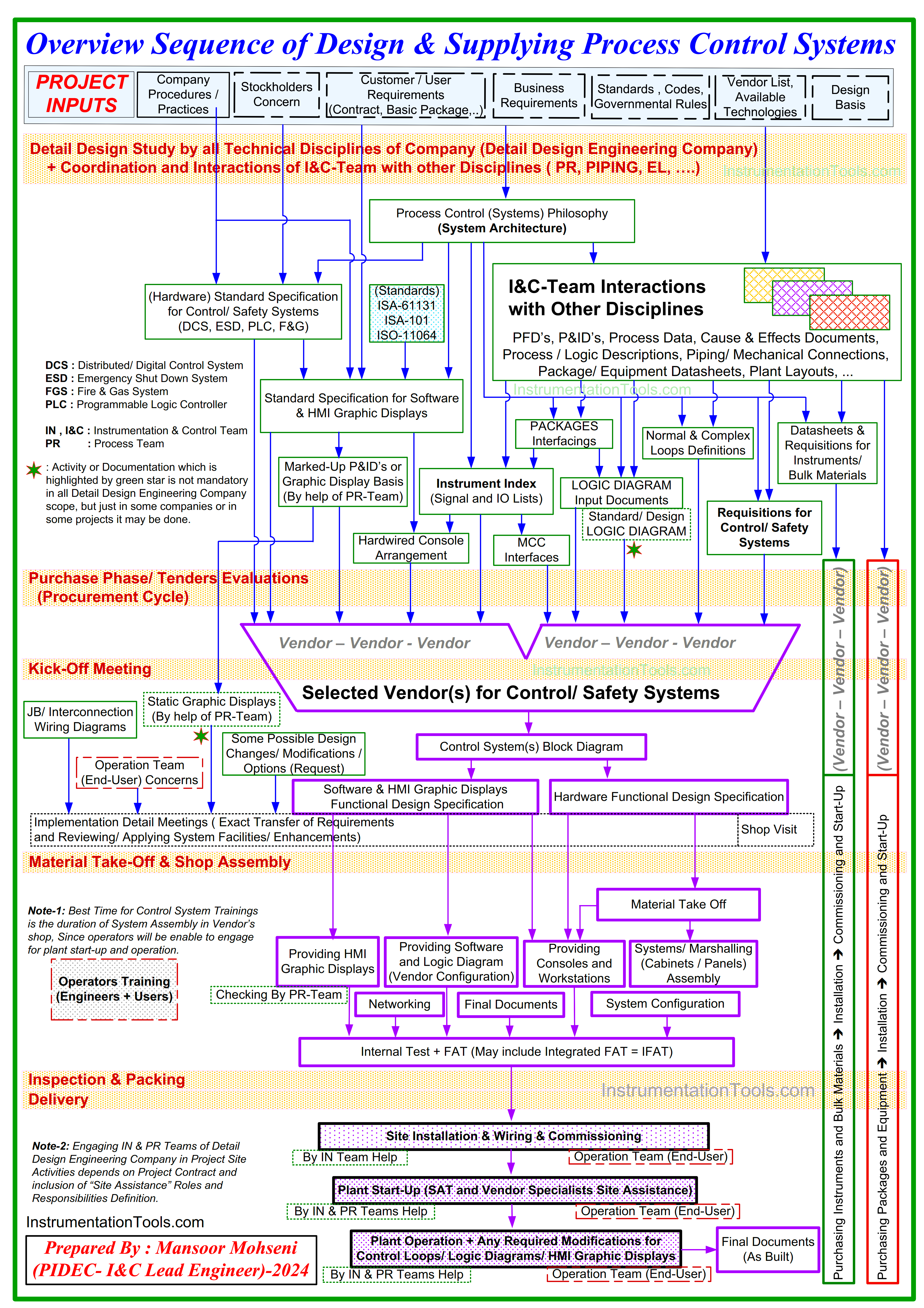
Figure-1: Overview Sequence of Design & Supplying Process Control & Safety Systems
ICSS:
An Integrated Control and Safety System is a common platform (from one vendor/ brand) for implementing all required Control and Safety functionalities for the Process Plant. Nowadays, such an integrated system is used for implementing at least DCS and ESD Systems (and even maybe FGS).
PLC:
A programmable Logic Controller System is used for the implementation of Control & Safety Functionalities of Packages (or even Processes of the Plant as BPCS).
PACKAGE:
A set of equipment and devices that are assembled to each other to provide some process functionality requirements (and usually handled by one technical discipline as package originator for purchasing it).
UCP:
A unit Control Panel is a set of cabinets or panels which include different types of systems and hardware for providing complete control and safety functional requirements of one Process Unit or Package (functionality) of the Process Plant Project. UCP may contain a PLC or Special Controller (such as an Electronic Governor) and other special systems (such as Machine Monitoring Systems).
PLC PANEL:
A set of cabinets or panels that includes complete hardware and software configurations of a PLC (Programmable Logic Controller) system to provide some control and safety functionality requirements.
AUXILARY (AUX.) PANEL:
A set of cabinets or panels that includes some special systems or accessory hardware, and provides additional Control and Safety Systems functionality requirements (such as Machine Monitoring Systems or Over-Speed Protection).
Package Control and Safety Systems
By developing the Process Control Systems Philosophy, the I&C-Team shall specify the required system and interfacings of each package and accordingly provide help for other disciplines (by providing required documentation and data further to close coordination for the definition of project requirements).
Although the design and supply of project packages will be done by activities of different teams and vendors via dedicated own cycles, however (as Figure-1 shows) some outputs of these activities and documentations will have effects on the design and supply of Process Control & Safety Systems (such as Packages Interfacings, Implementation of some Logic Diagrams, Providing some Normal and Complex Loops, Supplying some Instruments or Bulk Materials …).
Main Design Documents for Process Control and Safety Systems
By developing the Process Control Systems Philosophy, the I&C-Team also shall provide some documentation and activities (further to the provided System Architecture Diagram) for the required Control & Safety Systems and Instrumentations of the Process Plant.
More detail on such items can be found in some articles, but here we just refer to the main items to review the overview sequence of design and supplying Process Control and Safety Systems.
Standard Specifications
Based on project requirements and the results of the Process Control Systems Philosophy and by using Company Procedures/ Practices with applicable Standards, I&C-Team shall provide the required Standard Specifications (Hardware, Software, and HMI Graphic Displays) for different systems of the Project Plant.
Due to different procedures in engineering companies or based on project contractual items, the number and format of such documents may be varied as:
- Issuing dedicated documents for each type of system, and defining specific requirements (one for DCS Hardware, one for DCS Software, and one for ESD Hardware, one for ESD Software …).
- Issuing General (common) documents for defining common requirements of some types of systems, while adding some more detailed clauses for defining specific requirements of each system type (as an example specific reliability requirements for ESD system).
In any case, such documents are to be issued for defining the specifications/ requirements of all project systems (including DCS, ESD, PLC, F&G, and Packages/ UCP systems).
Instrument Index
All project signals and Instruments shall be listed in the Instrument Index and accordingly, relevant Signal and IO Lists of each system shall be extracted (and documented). The IO List document has an essential (vital) role in specifying the size of required systems.
Also, the IO type’s definition will specify which accessory items (such as isolation barriers or relays or even redundant IO cards/ channels/ loops) are needed for implementing required loops. However, the quantity of IOs in each Process Unit (in such a list) will help the system vendor to assign and arrange the suitable number of processor units for the execution of functionalities of all plants.
Figure-2 shows a sample of the DCS IO List which defines IO types and the quantities of IO applicable in each Process Unit. As shown in this figure, the IO List document may not be completed at an early stage of supplying Process Control and Safety Systems (Units 5000 and 5200 were not specified at the preparation issue date of the IO List document). Of course, such difficulty may add extra cost and time claims to the commercial contract for the required system and shall be discussed, scheduled, and finalized during the kick-off meeting between the purchaser and vendor.
Figure-2 shows that such document may show just required IO’s for Process Plants, and so the required spare IO signals (IO channels and relevant accessories) in any form (hot or cold) shall be specified by the purchaser to be considered by vendors in their offers. In some engineering companies, spare requirements may be mentioned directly in the IO List document.
Figure-2: Sample of DCS IO List which defines the IO Signal types and the required quantities for each Process Unit.
Communications and Interfacings
All required Communications and other types of Interfacings shall be investigated and documented accordingly. Such data and documents will specify the required communications and networks for the requested systems.
Logic Diagram Functionalities
All required functionalities of the project shall be investigated and documented accordingly. Such requirements may be reflected in different documents such as Cause & Effects Documents, Process Control Descriptions, etc.
In some engineering companies, the required basis of interlocks and logic is provided as a Standard/ Design Logic Diagram document for use and completed by the system’s vendor (but such a document may not be issued in other companies).
Normal & Complex Loops Definitions
Usually, definitions of Process Plant normal loops are reflected in the Instrument Index, but the procedure of defining such loops in Process Control/ Safety Systems shall be clarified or documented by the I&C team. However, for complex loops, they shall provide one document (such document may be merged with normal loop definitions).
Marked up P&IDs
Further to HMI Graphic Displays Specifications, Marked-up P&IDs shall be provided for implementing project HMI screen sheets by the system’s vendor.
In some Engineering Companies, the Static Graphic Displays document is provided based on Marked-up P&IDs, in order to speed up the implementation of graphic displays and increase the required quality in advance (and making lower comments for any modifications and saving the relevant time).
Preparation of Graphic display requirements and checking the implemented sheets (provided by the system’s vendor) will be done with the help of PROCESS Discipline.
Auxiliary Hardware
All required Auxiliary Hardware for implementing Process Plant functionalities (Such as Auxiliary Hardwired Console or MCC Interface Cabinets/ Panels) requirements shall be documented for transferring to the system’s vendor.
Purchasing Phase of Process Control & Safety Systems
After providing the required data and documentation for defining required Control & Safety Systems, relevant Material Requisitions shall be issued for starting the Procurement/ Purchasing Phase of required items.
The detailed steps of the Procurement Phase and relevant activities and correspondences can be studied in more detail via the article: “Procurement Service Cycle Definition” – Engineering Practice Magazine – July 2024 (IACPE).
Supplying Process Control & Safety Systems
After vendor selection and by starting their activities, the I&C-Team shall have close coordination with the system vendor for finalizing their documents and assembling/ configuring the required system (by transferring data and requirements, attending meetings, reviewing and making comments on vendor documents, shop visits, following acceptance tests, and finally site assistances) as shown in Figure-1.
Since from this time system’s vendor has the main role in configuring the required system, the details of such activities and correspondences and vendor actions are to be studied by another article.
Material Requisition for Process Control & Safety Systems
During activation of the procurement/ purchasing phase of Process Control and Safety Systems (similar to other requisitions), the provided Material Requisition Document has a vital role in completing the cycle of supplying such items (with exact schedule and minimum conflicts or any mismatching). So we will have some review on main contents of such document.
Scope of Work
The first section of Material Requisition shall define all required activities of the vendor which are expected to be done by them. Figure-3 shows sample of one realistic section included in DCS Requisition. As it is clear, the scope of work of all activities shall be clarified as Main or Option in body of the offer.
On the other hand, Main items are considered as mandatory items inside the offer (or final contract), and the option items shall be explained in offer, while after agreements in more detail discussions or during the meetings (especially in Kick-Off Meeting) may be considered as main or conditionally responsibility of vendor (in final contract).
As an example, usually “Training” is considered as an option, since the quality and the required contents of training are not so clear at the early time of the bid stage of the procurement cycle, while details of such items can be specified after some more clarifications in future steps. As it was seen although the “Training” may be conditionally added (or even ignored), but vendor shall know the responsibility of presenting such work in their scope.
As Figure-3 shows, the vendor shall inform the purchaser of any additional scope of work (which is missed in the first table) before signing any official contract. This item can prevent any future discussion on unapparent works, since in the summary explanation, it was mentioned that vendor scope is not limited to this table.
Figure-3: Scope of Work Section of Distributed Control System (DCS) Requisition
Scope of Supply
Similar to the Scope of Work, Material Requisition shall include a Scope of Supply section for defining all required items to be supplied by the vendor. Figure-4 shows a sample of one realistic section included in the DCS Requisition. Here again, we can see that, it shall clarify the Main and Option items.
As an example, 2 years of spare parts shall be supplied by the vendor while the amount of them shall be finalized after all clarification discussions and resulting agreements. Similarly, capital spare parts may have a big cost or may be not applicable.
Here again in order to prevent any future discussion, the vendor was asked to recommend any possible supply items too.
Requisition Notes
In the requisition Notes section of Material Requisition, the vendor is guided on how to provide the requested offer and its attachments completely based on project requirements and considered rules and conditions.
However, the details or exact decisions on some items (which may have different solutions in the attached specifications or documents) are clearly mentioned in this section. Furthermore, any insisted items are mentioned here to remind the vendor too.
If the vendor has any other concerns, then in the final revision of the Requisition, the results of all agreed or discussed items (between purchaser and vendor) are mentioned as official agreements.
Figure-5 shows a sample of one realistic section included in DCS Requisition.
As an example, we can see in this figure (item 3.8) that the vendor is requested to provide breakdown prices for all recommended spare parts further to other required data and documents such as a complete part list and sectional drawings, and so on. This note is very important since the requested system has so many items and some of them have big quantities (such as IO cards), while the price of them may vary due to the quantity of quoted items.
On the other hand, vendors may have different prices during the time and so they shall clarify the prices for considered duration periods or times. Furthermore, part lists and sectional drawings can help purchaser for decision on quantity of common items which may be used in different equipment or devices.
Another example in this figure (item 3.10), explains the inspection and test procedure applicable to this project and at the end insisted on “In any case, the shipment cannot be made without written approval from the purchaser as ‘Release note for shipment’.”
Figure-4: Scope of Supply Section of Distributed Control System (DCS) Requisition
Figure-5: Requisition Notes Section of Distributed Control System (DCS) Requisition
Material List
The material list section of Material Requisition shall define different items and relevant quantities of system arrangement. This section is general Material Take-Off (MTO) and shall be completed as more detail by the vendor.
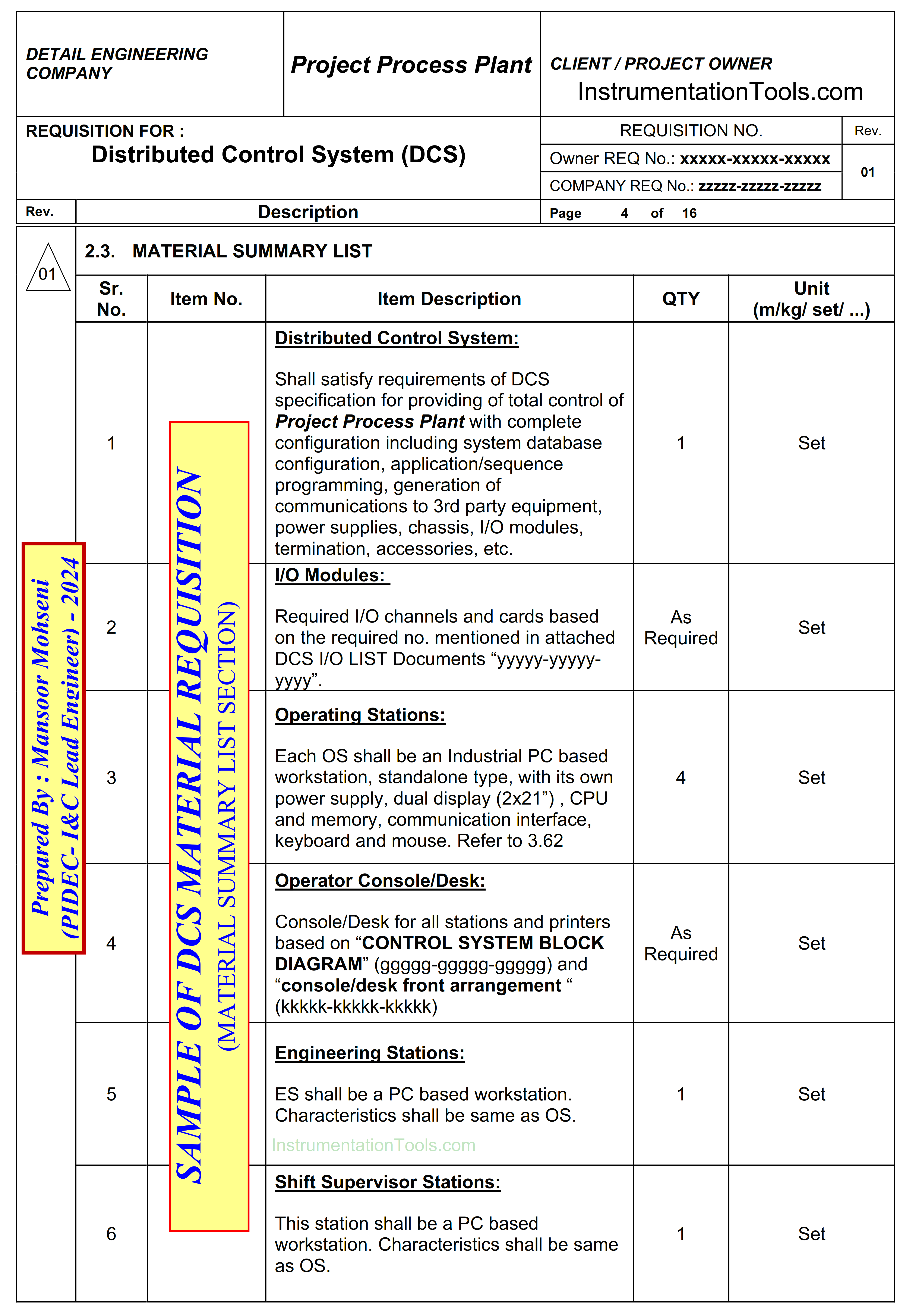
Figure-6: Material List Section of Distributed Control System (DCS) Requisition
List of Attachments
The list of Attachment section of Material Requisition clarifies the list of all provided documents which shall be considered as reference by the vendor for the preparation of the relevant offer.
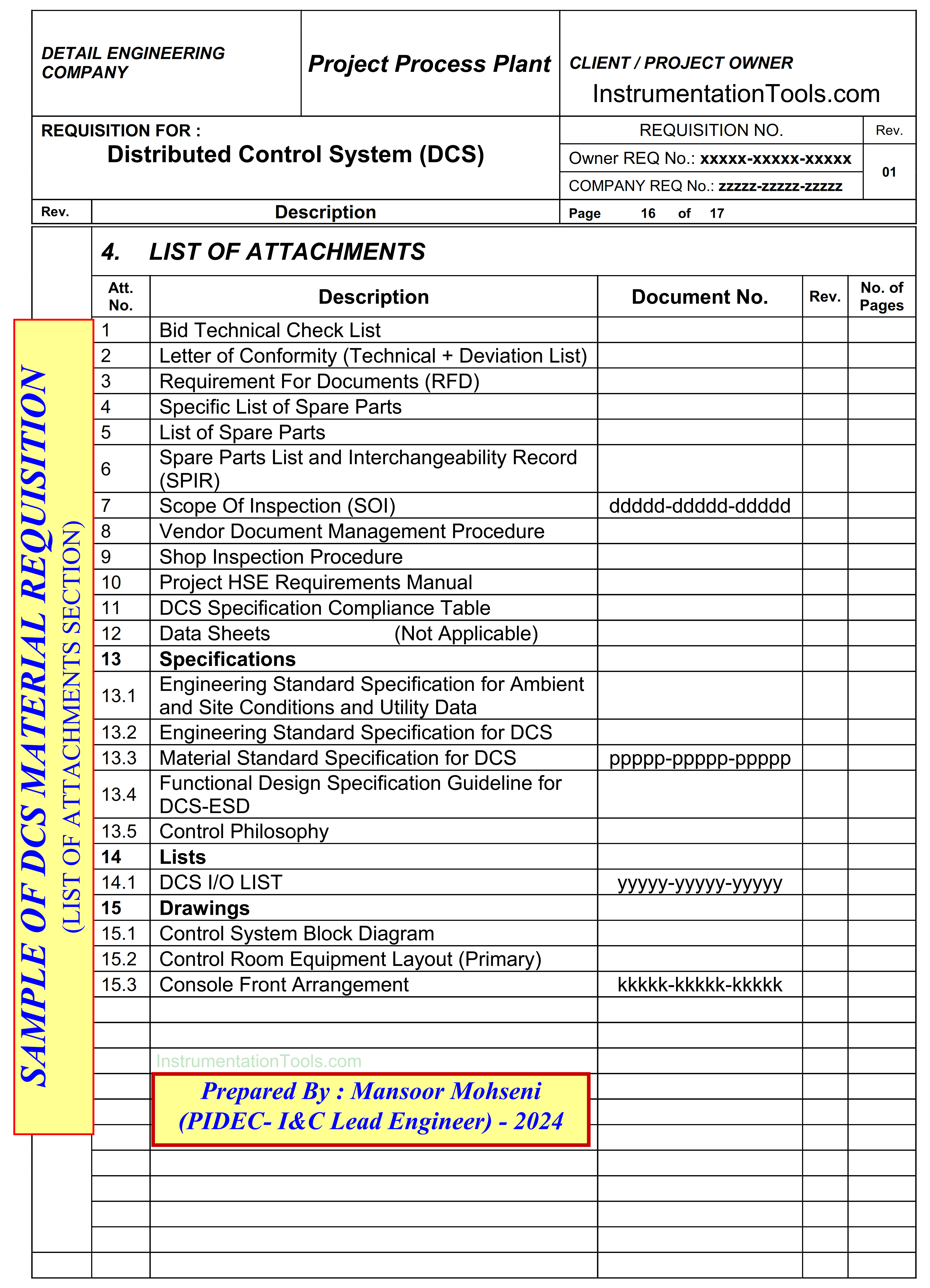
Figure-7: List of attachments of Distributed Control System (DCS) Requisition
Letter of Conformity
Letter of conformity is one of the System Requisition attachments which shall be filled and officially signed by vendor in order to clarify how much they followed project requirements in preparation of their offer. On the other hand, they shall add the official deviation list to this document and it will be the future reference for judge on any probable deviations which may be found in final job results.
Purchaser shall study such deviation list during the BID stage and negotiate with the vendor on any possible modifications/ changes or otherwise consider it in their future activities and functionality designs and operations.
Conclusion
I&C-Team of Detail Design/ Engineering Company shall do some activities and provide some documents for design and supplying Process Control and Safety Systems (of Process Plant Project) based on project requirements and developed Process Control Systems Philosophy (as shown in Figure-1).
Generally, it can be said that their responsibilities are divided into two parts. The first part is from the project start-up to selecting the system(s) vendor, while the second part is after vendor selection. Material Requisition document is one of the most important documents for ending the first part, and some of the main sections of such document were reviewed in this article. The second part of I&C-Team responsibilities will be reviewed in another article.
References:
- Vendor View of Supplying Process Control Systems
- Process Control Systems Philosophy Concept
- Interactions With Process Control Systems Philosophy
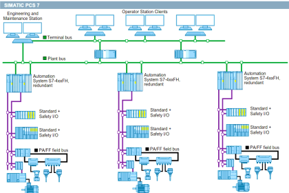
- Vendor Document for Project System Architecture
- System architecture and process control systems philosophy
- Instrumentation Design Engineer Roles & Responsibilities