During the execution of an Industrial Process Plant Project, the instrumentation (I&C) Team shall Transfer Project Requirements (functionalities) to a suitable format of Data and Documents, in order to enable systems vendors to implement Project Control & Safety System Aspects (based on considered Process Control & Safety Systems Philosophy).
I&C Team during the development of the required project Control & Safety Systems aspects (functionalities) cycle, shall have different roles and responsibilities which can be reviewed in the reference article.
However, in some Detail Design Engineering Companies, the I&C Team usually provides a Design Logic Diagram (document) by using standards and their practices for a clear and complete interpretation of the required project interlocks/ logics. In this article, we will review some considerations in this regard.
Project Required Functionalities in the form of Interlocks/ Logics
In all Process Plant Projects, some required process functionalities can be defined or expressed using conditions and process results via some binary status signals. For such cases it is possible to use some standard symbols (which are usually known as gates) for defining the combination of conditions and producing the target results. Some of common functional logic symbols are shown and defined in Figure-1.
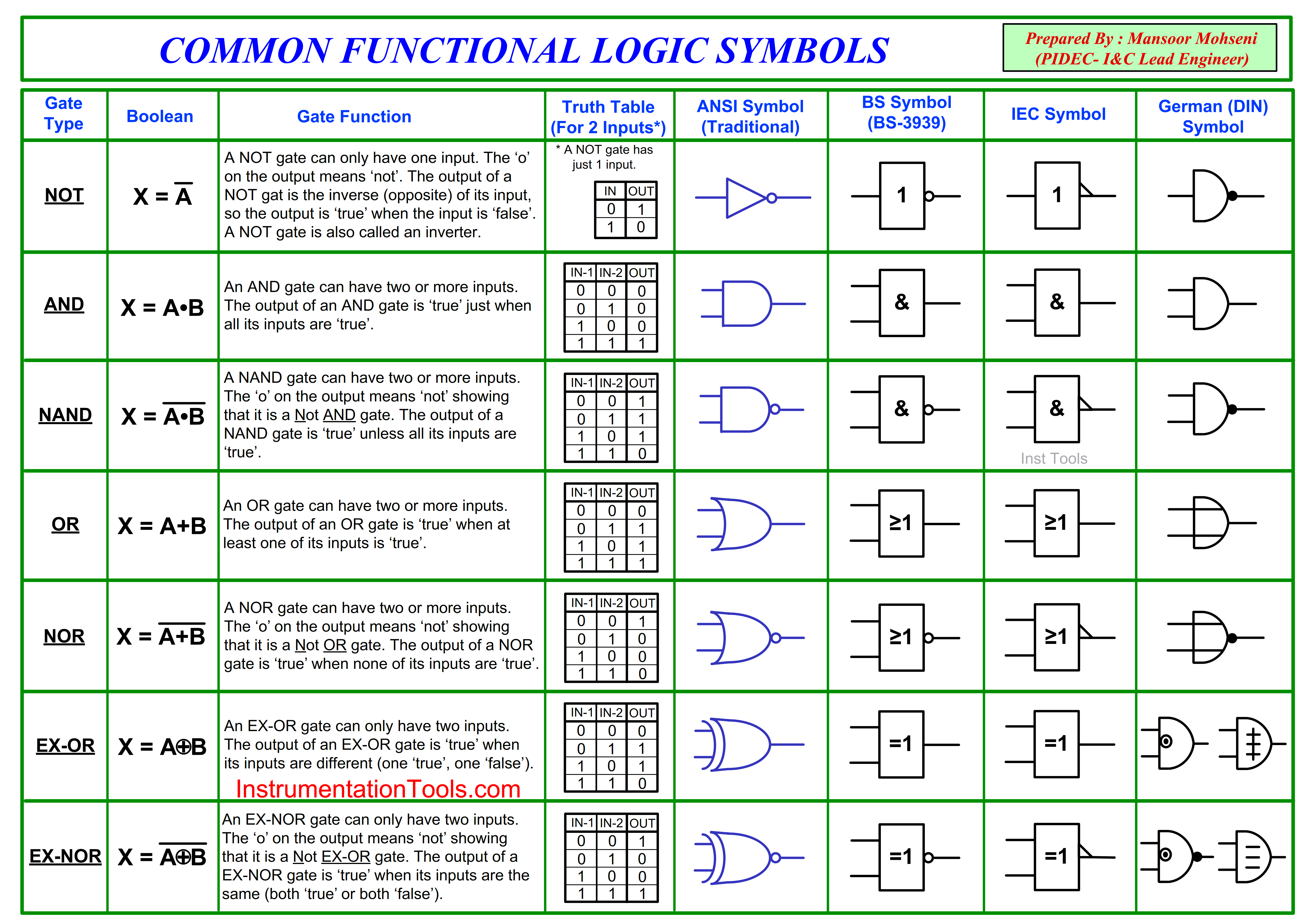
Figure 1: Common Functional Logic Symbols and Definitions
As Figure-1 shows, there are different standard ways to show or express the required functional logic gates.
The most famous standard that is considered for the definition of some exact symbols on Gates and Logical Functional Blocks (in Process Plants) is ISA5.2. The exact title name of this standard is “Binary Logic Diagrams for Process Operations” as shown in Figure-2.
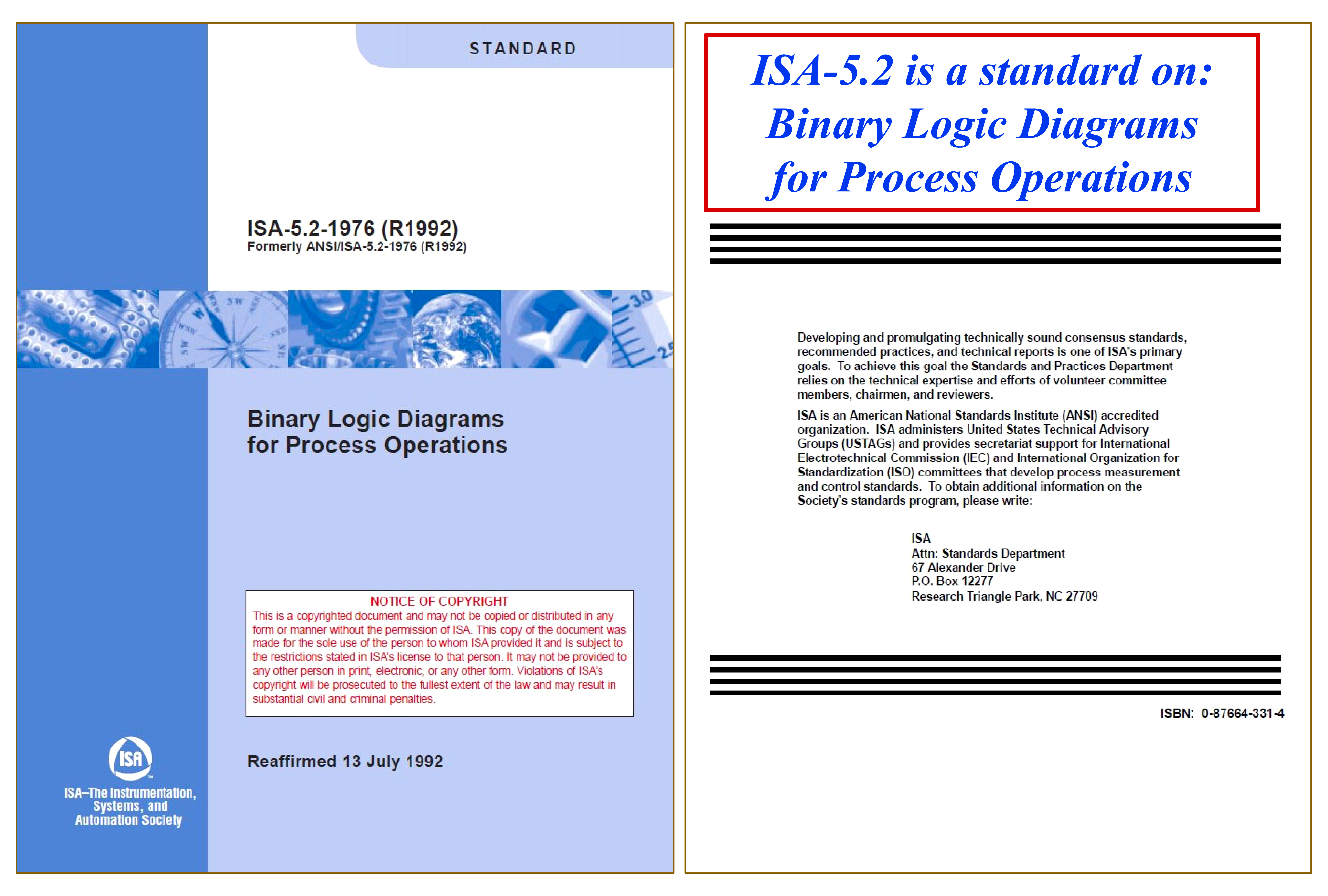
Figure-2: ISA5.2 as standard on “Binary Logic Diagrams for Process Operations”.
As expressed in the early pages of this standard, the purpose of it is: “The purpose of this Standard is to provide a method of logic diagramming of binary interlock and sequencing systems for the startup, operation, alarm, and shutdown of equipment and processes in the chemical, petroleum, power generation, air conditioning, metal refining, and numerous other industries.” (See Figure-3).
So we can conclude that this standard provides a method to change the project requirements functionalities (Startup, Operation, Alarm, and Shutdown of Equipment and Processes) in the form of a Logic Diagram to be implemented in binary interlock and sequencing systems in different types of Process Plant Industries.
Also, it has been declared that: “The Standard is intended to facilitate the understanding of the operation of binary systems, and to improve communications among technical, management, design, operating, and maintenance personnel concerned with the systems.” (See Figure-3).
So we can conclude that this standard provides some facility (tool) for (better) understanding the operation of binary systems operations on implementing project requirements, and furthermore, it provides an improvement on communications between different parties (specialists) of the Process Plant project. On the other hand, it explicitly mentioned that this standard is useful for different specialists (further to the I&C Team and to be studied by all of them) for Process Plant operations execution and development improvement.
In the scope definition of this standard, we find that: “The Standard is intended to symbolize the binary operating functions of a system in a manner that can be applied to any class of hardware, whether it be electronic, electrical, fluidic, pneumatic, hydraulic, mechanical, manual, optical, or other.” (See Figure-3).
So we can conclude that this standard is applicable for (approximately) all hardware systems with the ability to execute binary operating functions, and is not related to any special purpose or dedicated system. In fact, it helps us to use it for applying the method of changing the project requirements to a standard format applicable in most of the existing systems without any anxiety or doubt about the type, brand, or model of the system.
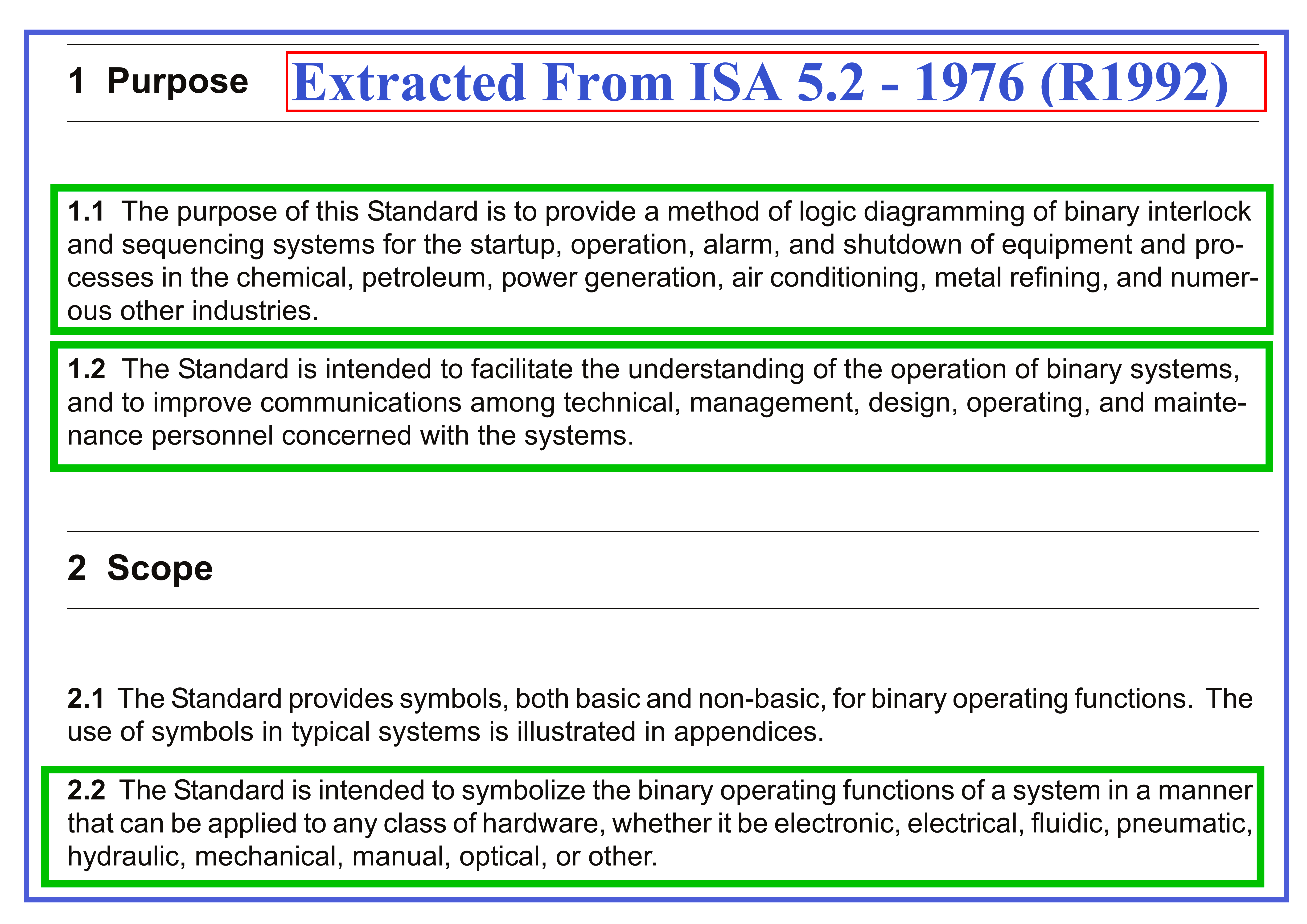
Figure-3: The Purpose and Scope of ISA5.2 Standard.
The exact definition of common symbols (as basic and non-basic) for binary operating functions and the procedure of using such symbols are explained in this standard.
Generally, it was mentioned that: “By using the symbols designated as “basic,” logic systems may be described with the use of only the most fundamental logic building blocks. The remaining symbols, not basic, are more comprehensive and enable logic systems to be diagrammed more concisely. Use of the non-basic symbols is optional.
A logic diagram may be more or less detailed depending on its intended use. The amount of detail in a logic diagram depends on the degree of refinement of the logic and on whether auxiliary, essentially non-logic, information is included.”
Figure-4 shows some of the basic functional blocks (logic symbols) that are explained in the ISA5.2 standard.
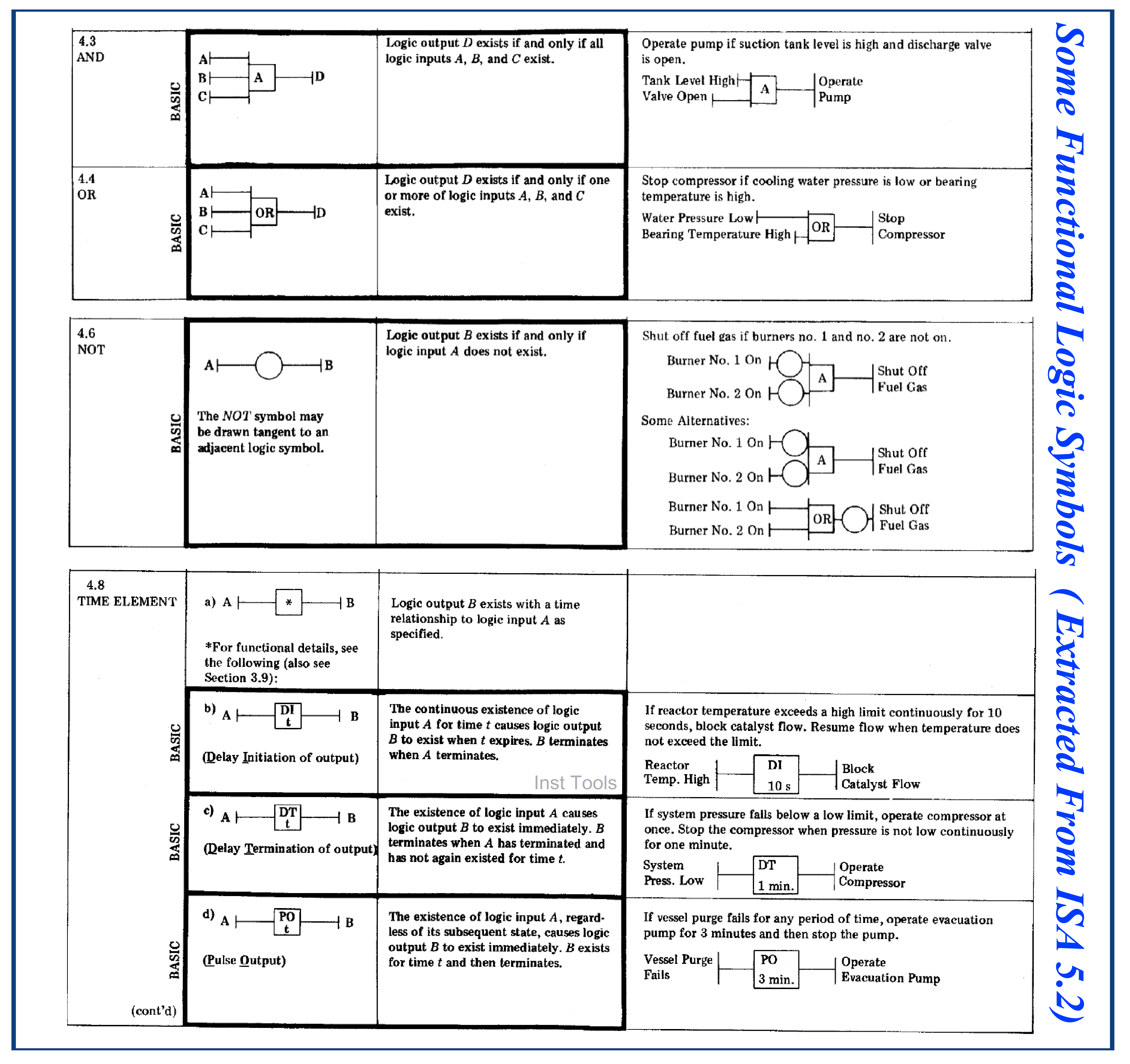
Figure-4: Some of the Functional Logic Symbols explained in ISA5.2 Standard.
Functional Blocks or Symbols defined in ISA5.2 shall be combined to each other by proper connection lines to create an Interlock Logic Diagram which is a reflection of defined signals in Project Process P&IDs and required functionalities reflected in project documents such as Cause & Effects Diagram or Process Descriptions. The Process Control & Safety Systems Operation/ Logics Implementing Cycle article provides further advice for better implementing Interlock Logics can be reviewed in the reference article. However, Figure 5 shows an example of an Interlock Logic Diagram shown in the ISA5.2 standard.
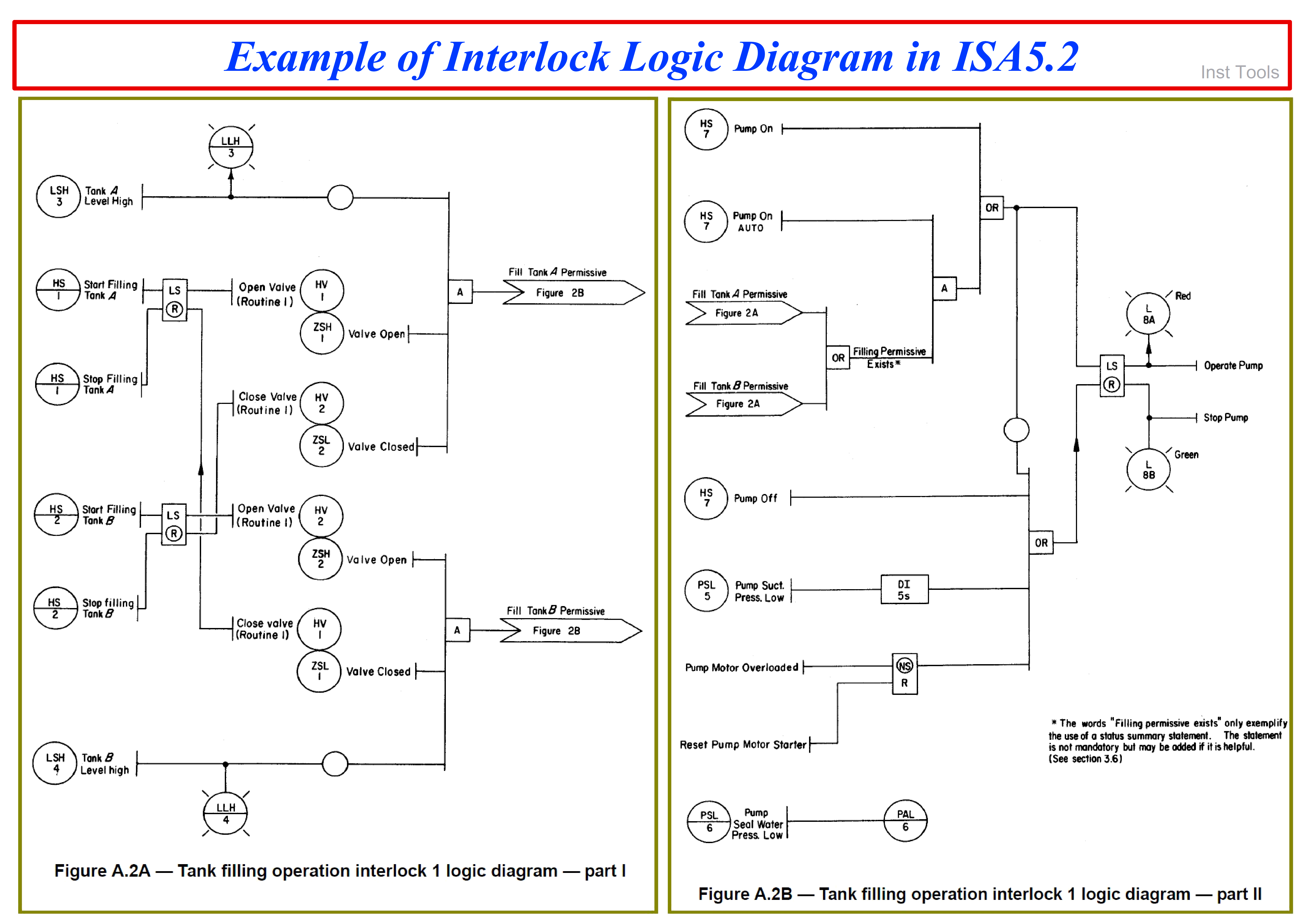
Figure-5: An example of an Interlock Logic Diagram Shown in ISA5.2 Standard.
Different Formats of Showing Logic Symbols
Although the ISA5.2 standard is a good reference for making convergence on a better understanding of (required) process functionalities, but usually the Design Logic Diagram Document may be provided by using different symbols indications (while they are equal to those ones defined in the mentioned standard).
In fac,t the symbols may be shown differently, but the concepts of Logic Diagram are still the same as ISA5.2. Referring again to Figure-1 we can see some equal indications of Logic Functional Blocks in other possible symbols (by different standards). Now a days, the IEC standard symbols (or similar British BS standards) are used more by Detail Design Companies.
Some Advantages for Producing Design Logic Diagram Document
Usually providing the Interlock Logic Diagram Document is not mandatory for the scope of Detail Design Engineering Companies, but providing such documents may have some advantages such as the following.
- As mentioned in ISA5.2 standard, it makes better understanding between different technical parties of the project (I&C and Process/ HSE Teams, and Client or their Consultant Specialists) on Process Functionalities.
- It will accelerate the Control & Safety Systems Vendor’s activities for implementing required project functionalities. It shall be noticed that Design Logic Diagram can be easily understandable and implementable by them, while without such document they shall study all project requirements (reflected in different format documents or data) and spend a lot of time and man-hours for combining them.
- Such a document will help greatly the Control & Safety Systems Vendors in estimating the project size and required scope of work (at Analysis Step by them).
- Such a document provides a very good reference basis for checking the compliance of configured (control & safety) systems on required project functionalities during acceptance tests (FAT & SAT).
- Such documents can be used by operation personnel to care about required process functionalities and their critical set-point consequences, especially during the Start-up Phase of the project.
- Such a document provides a very good reference basis for studying the required process operation changes and the possible effects (via all engaged specialists) after plant operation or during plant maintenance. It shall be noticed that the Interlock Logics implemented in configured (control & safety) systems are much more complicated than the Design Logic Diagram (which is easily understandable by all). In fact, the implemented/ configured Interlock Logic in (control & safety) systems may be understandable by the I&C Team and very seldom by other specialists.
- Such document may be used for providing Graphic Displays for simplified Logic Diagram of Process Plant and monitoring the overview of Process critical signals.
- Providing such documents by Detail Design Engineering specialists may improve and guarantee the better implementation of project requirements via (control & safety) systems, since they may have more experience or understanding of project process requirements than systems vendors since they have the facility of inline help of all engaged specialists (especially Process/ Safety Teams).
Although providing Design Interlock Logic Diagram Documents by Detail Design Engineering Companies will have great advantages (some of them mentioned above) but in order to prevent any future discussions or conflicts on the boundary limits of systems vendors, they may prefer to ignore producing such document. In fact, systems vendors shall know (or be aware) that the scope of their works is not limited to functionalities mentioned in Design Interlock Logic Diagrams, but if such concern was not agreed upon during the contract phase, it may produce some conflicts or discussions on the scope of implementation of the facilities (in project execution).
Also it shall be noticed that providing such a document needs complete competencies of the I&C Team on required skills and practices further to the familiarity of them on applicable standards (ISA5.2, IEC-61131.3,…) and providing Logic Diagram facility tricks. They shall have good coordination with others too.
Some advice for Better Providing an Interlock/ Logic Diagram
Here we try to review some advice for better providing an Interlock/ Logic Diagram.
- Follow suitable procedure for defining Signal Tag Numbers and integrity of complete project documentation on defining required process functionalities. (The reference article may offer some good guidelines in this regard).
- At the beginning of the Interlock Logic Diagram show and define all common (used) symbols and relevant considered functions as Legend Sheet. Figure 6 is an example of such a definition (legend) sheet. It shall be noticed that definition of some symbols may need additional tables or (timing, functional) diagrams.
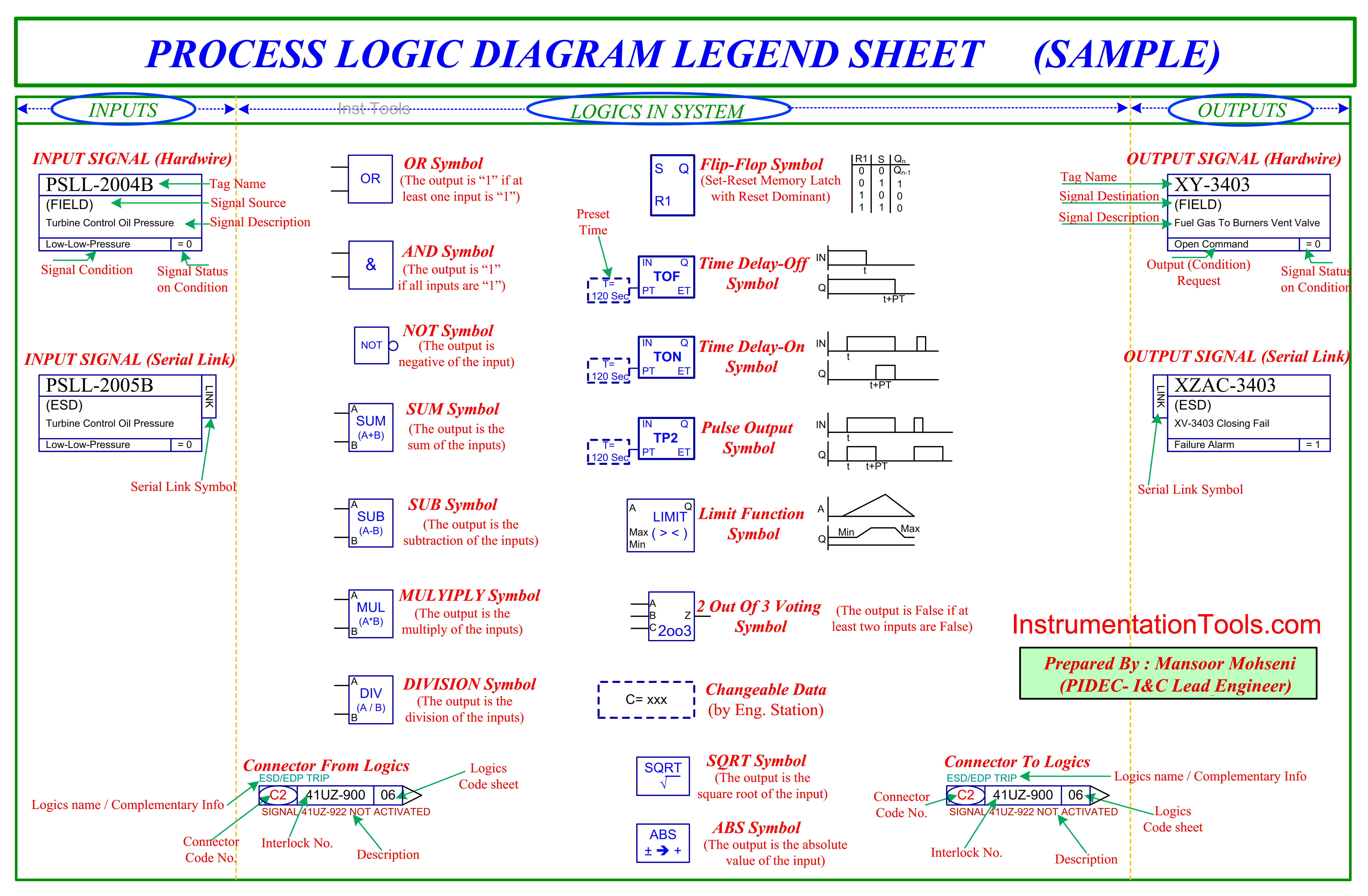
Figure-6: A sample of Interlock Logic Diagram Legend Sheet.
- As Figure 6 shows (and some future figures too), the proposed format exactly defines the different areas in document sheets that are considered for Inputs, Outputs, and (functional) Logic in the System.
- Some special (non-basic) functional blocks shall be defined in the early sheets of the document (after the legend sheet) too. Figures 7 to 9 show three samples of such special function block definitions.
- It shall be noticed that usually provided logic diagrams will have effects on binary signals, and so the analog signals shall be process suitably first for making binary signals (maybe as different alarm levels as shown in Figure-8).
- The override function on some signals shall be defined clearly (see Figures 7 and 8).
- Complex calculation/compensation blocks shall be defined clearly. Figure-9 shows an example of the Pressure Temperature (PT) Compensation of Flow Measurement.
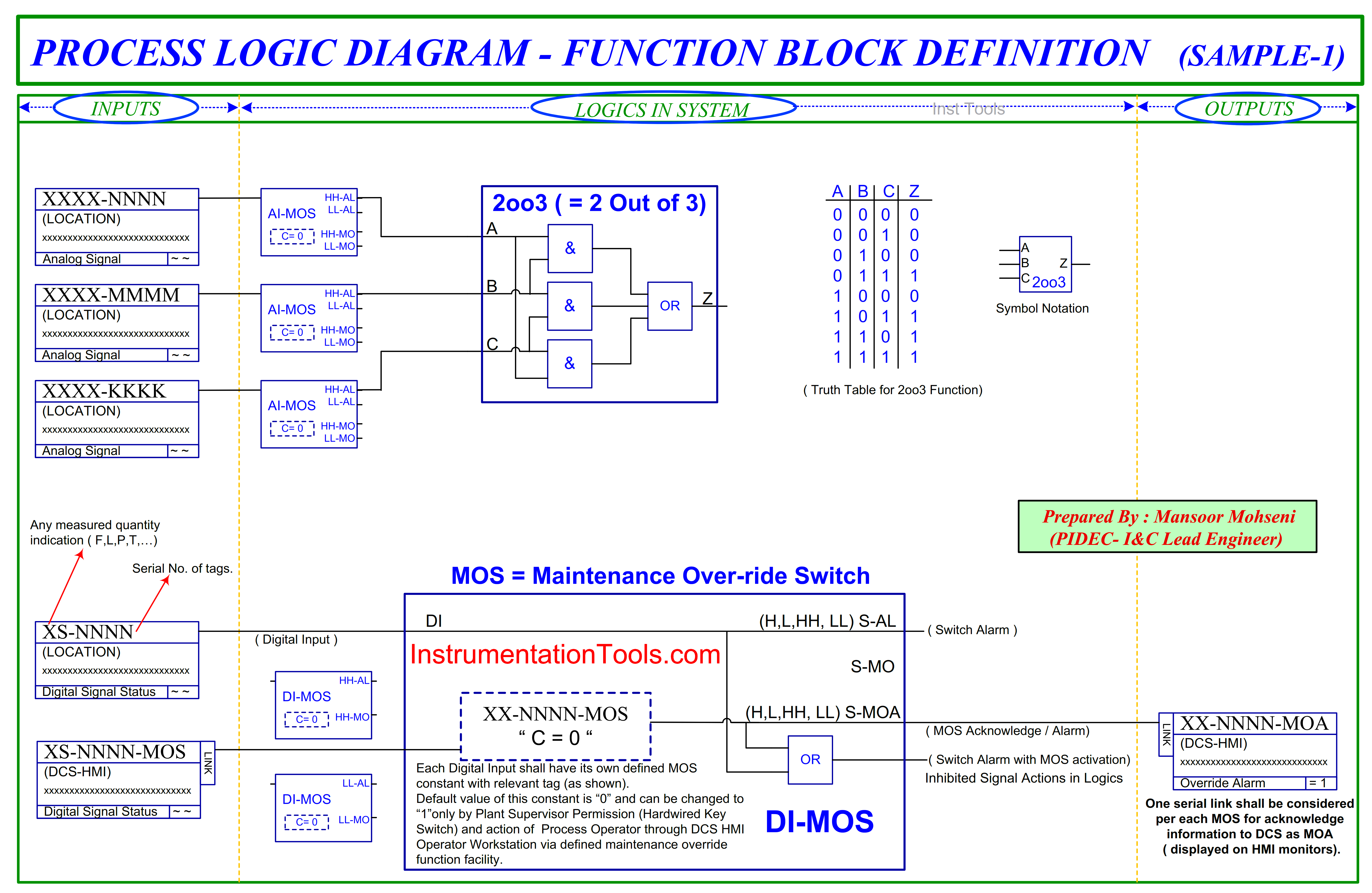
Figure-7: Function Block Definition sample-1 in Interlock Logic Diagram.
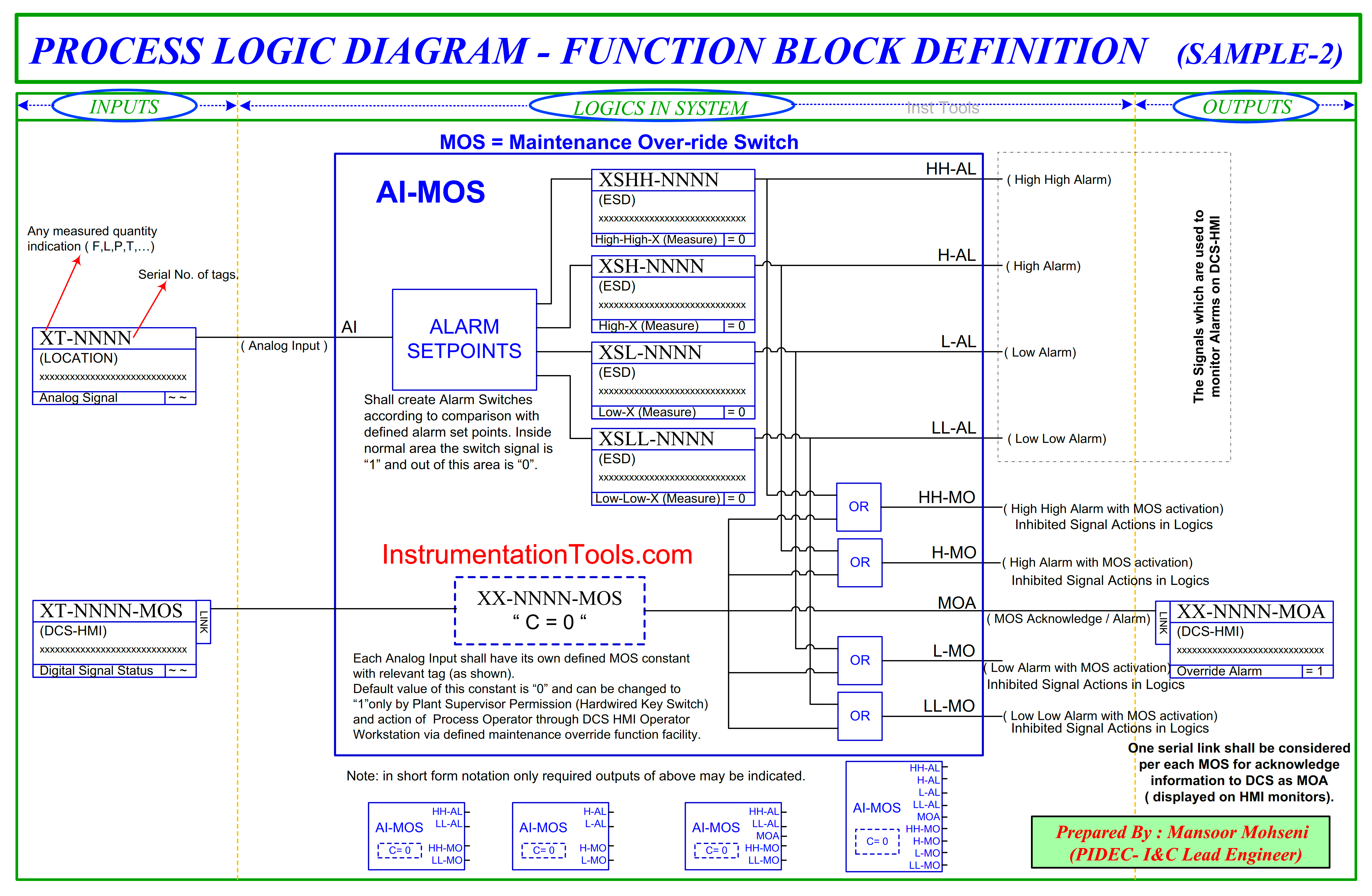
Figure-8: Function Block Definition sample-2 in Interlock Logic Diagram.
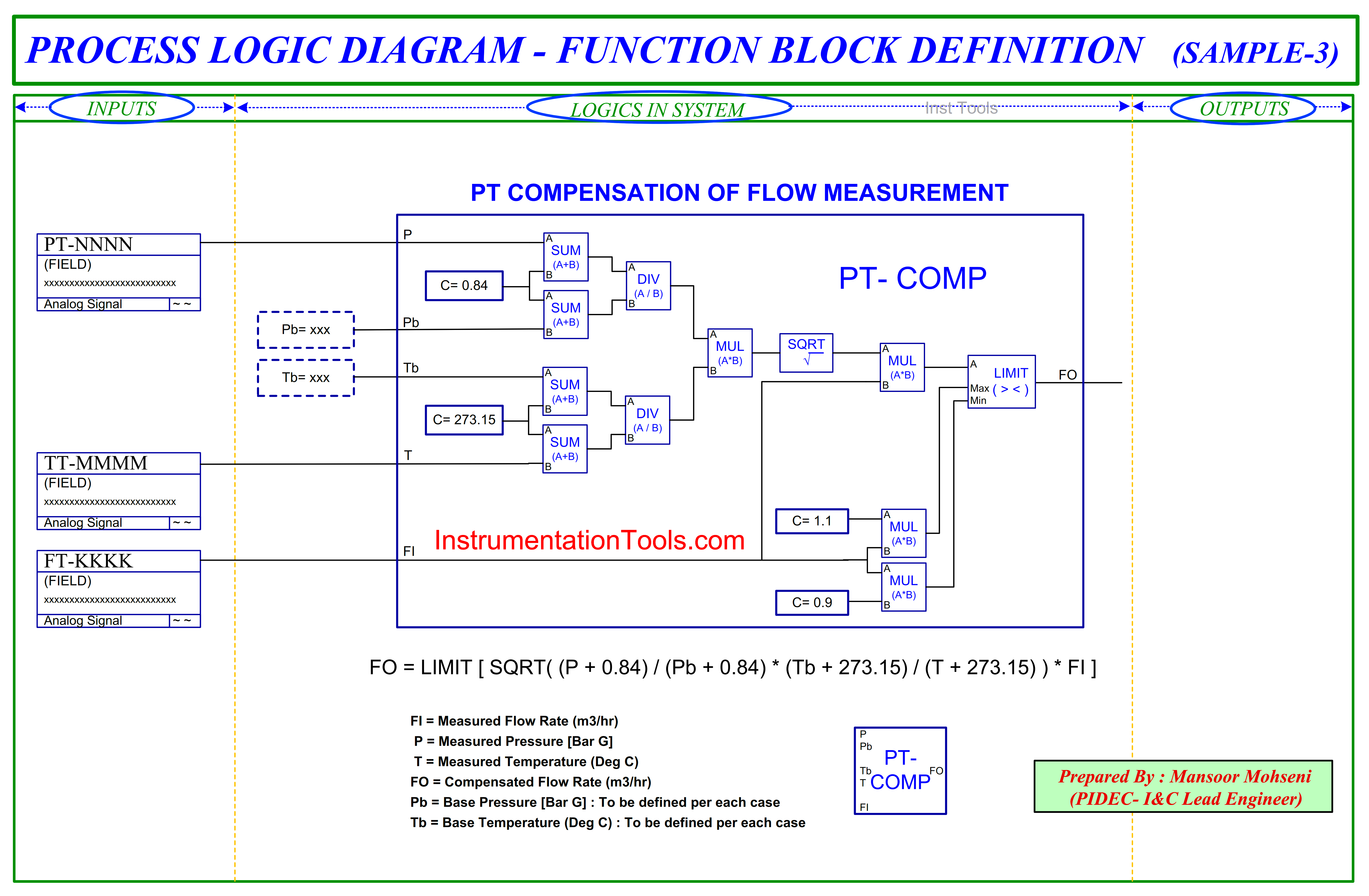
Figure-9: Function Block Definition sample-3 in Interlock Logic Diagram.
- Consider all Input Signals on the left side of the sheets and after the combination of them, make output signals at the right side of the sheet. (See Figure-10)
As much as possible make the Logic Section simple with regular formats on connection lines and sequence of execution of function blocks too.
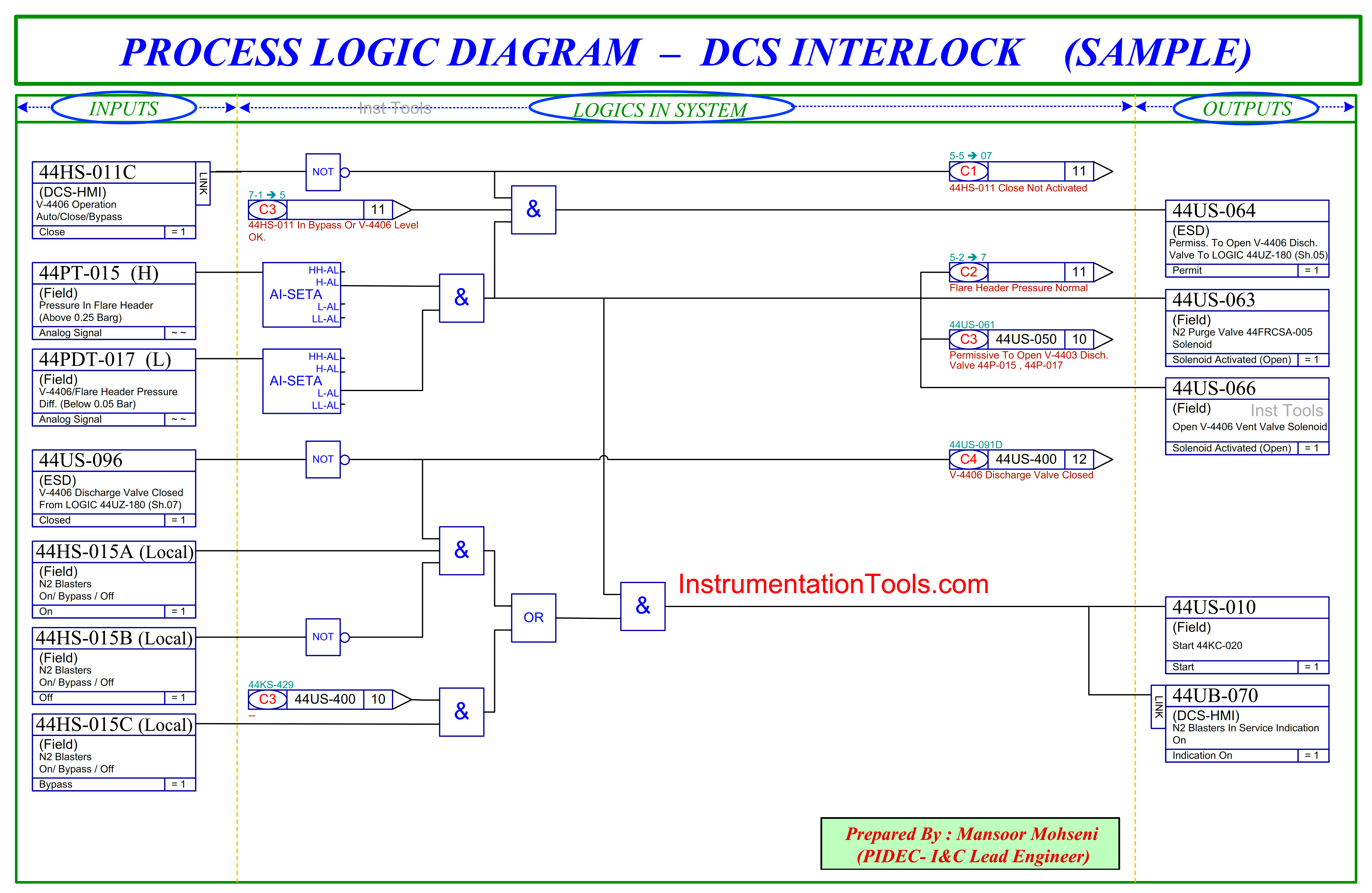
Figure-10: DCS Interlock Logic Diagram Sample.
- Insert all related information of input and output signals at properly considered places in the block. For example, such information may include Tag number, System/ Location, Signal Description, Function, and especially the status of the signal on defined action. (See Figures 10 and 11)
- Instead of Integrated Function Blocks for Inputs or Outputs, you may use another format of Logic Diagram which includes different sections for different systems or locations (See Figure-12).
- All arrow connection signals shall have complete information regarding the exact source or destination of the connector (See Figures 10 and 11).
- Each sheet of Interlock Logic Diagram document shall have its own unique sheet number which is usually used in reference source or target destination of connector symbols. If such a document includes many Interlock Logic Numbers, each one may have its own sequence numbers (in this case you may find similar sheet numbers but in different Interlock Logic Numbers). For example, you may have sheet numbers 1 to 10 in both interlock numbers I-4201 and I-4401 (or any other interlock numbers).
Also, you may define sheet numbers based on the Interlock Logic Number sequence and use Page Numbers relevant to the whole document. In any case, such number(s) shall be clearly indicated in the overall frame format of each sheet (not shown in our examples, since it may be a company standard frame).
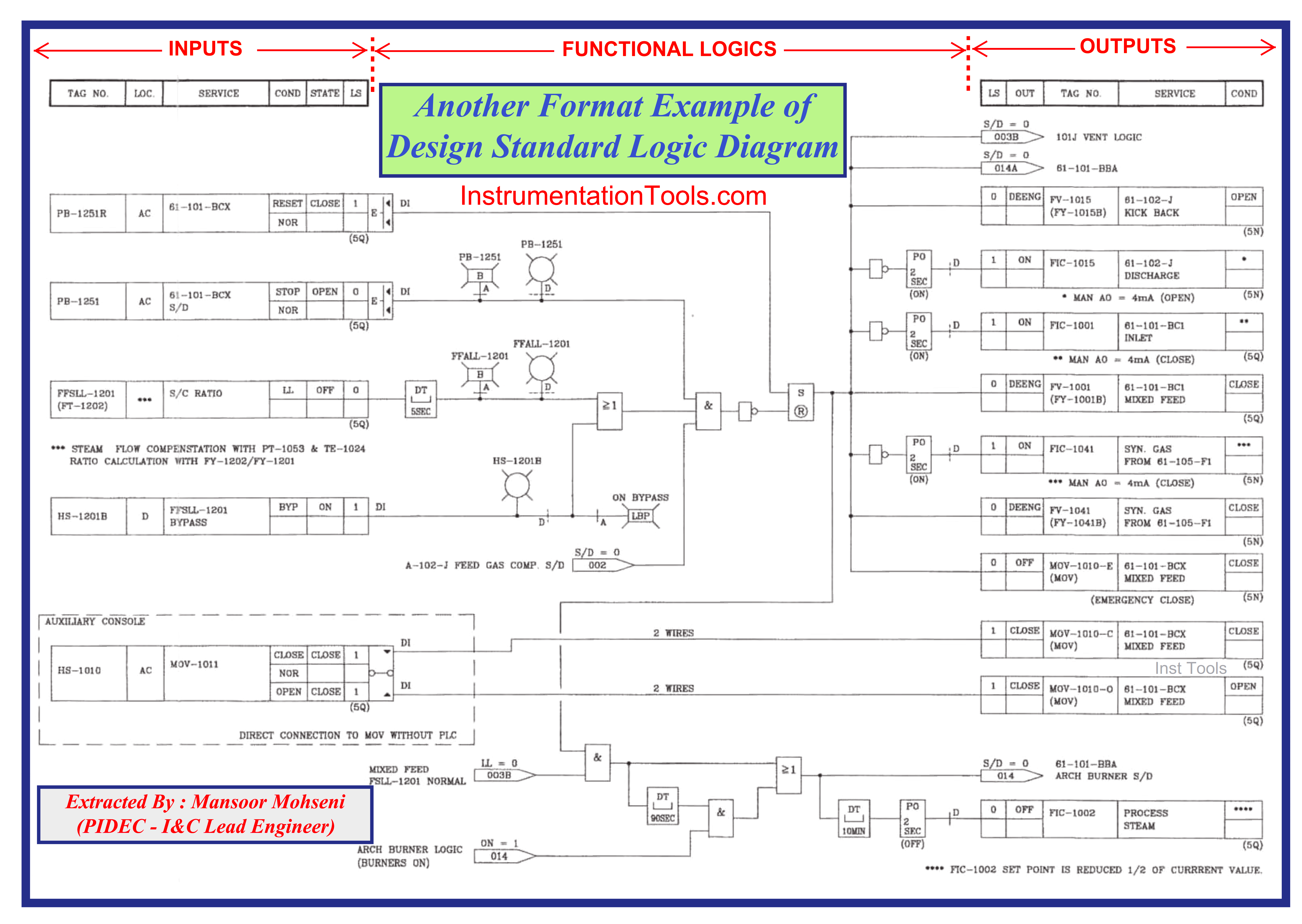
Figure-11: Another Format Example of Design Standard Logic Diagram.
Figure-12.1: Another Format Example of Design Standard Logic Diagram.
Figure-12.2: Another Format Example of Design Standard Logic Diagram.
Interlock/ Logic Diagram for Packages
Similar to describing some Process Functionalities by (standard) Design Logic Diagram, each Process package of the project may have its own Design Logic Diagram which shall be supplied by the Package Vendor for clarification on implemented functionalities in relevant (control & safety) systems. Figures 13 and 14 show two extracted samples of Interlock Logic Diagrams provided by Packages Vendors.
Figure-13: Extracted sample of Package Logic Diagram.
Figure-14: Another extracted sample of Package Logic Diagram.
The System Logic Language
Here we shall strictly mention that, although the Design Interlock Logic Diagram is the basis for implementing required process functionalities in the (control & safety) systems functional logic facilities, but it may be implemented by different languages defined in IEC-61131.3 standard.
On the other hand, the implemented logic in (control & safety) systems may appear in different formats and symbols. Figure 15 shows a sample of the design Logic Diagram which may be implemented in the system via the Ladder Diagram Language. Different Languages of Logic implementation in systems facilities are out of the scope of this article.
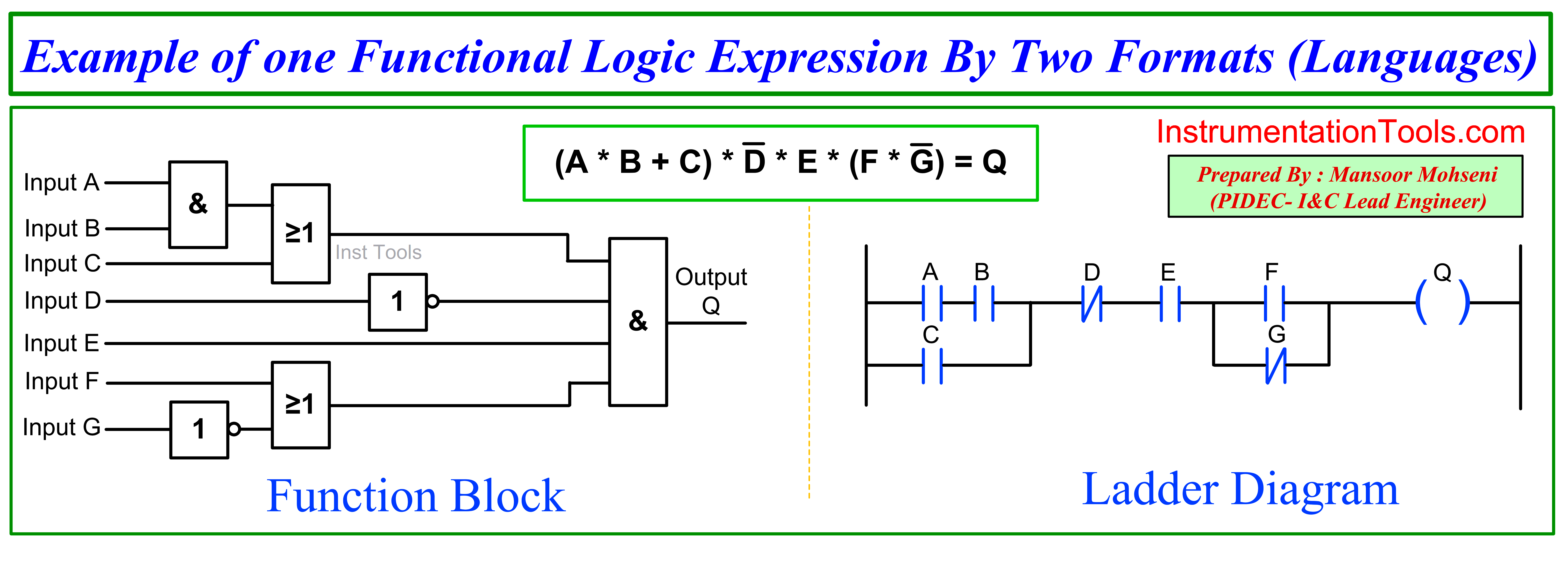
Figure-15: Design (Functional) Logic Diagram versus Logic Diagram Implemented in System by Ladder Diagram.
References:
- Process Control & Safety Systems Logics Implementation Cycle
- The Instrument Engineer Job Roles & Responsibilities
- Design View of Supplying Industrial Process Control Systems
- Vendor View of Supplying Industrial Control & Safety Systems