In Rockwell automation, one of the most used software is Studio 5000 and FactoryTalk View Studio. Many new programmers who want to work on this platform often tend to learn new things on it, due to the vast variety of features it offers.
Also, it is very user friendly and makes programming very quick to understand and design. So, before developing a project, it is necessary that some basic concepts are understood first which can aid it quickly.
In this post, we will learn how to design a sample project using Studio 5000 and FactoryTalk View Studio.
Studio 5000 and FactoryTalk View Studio
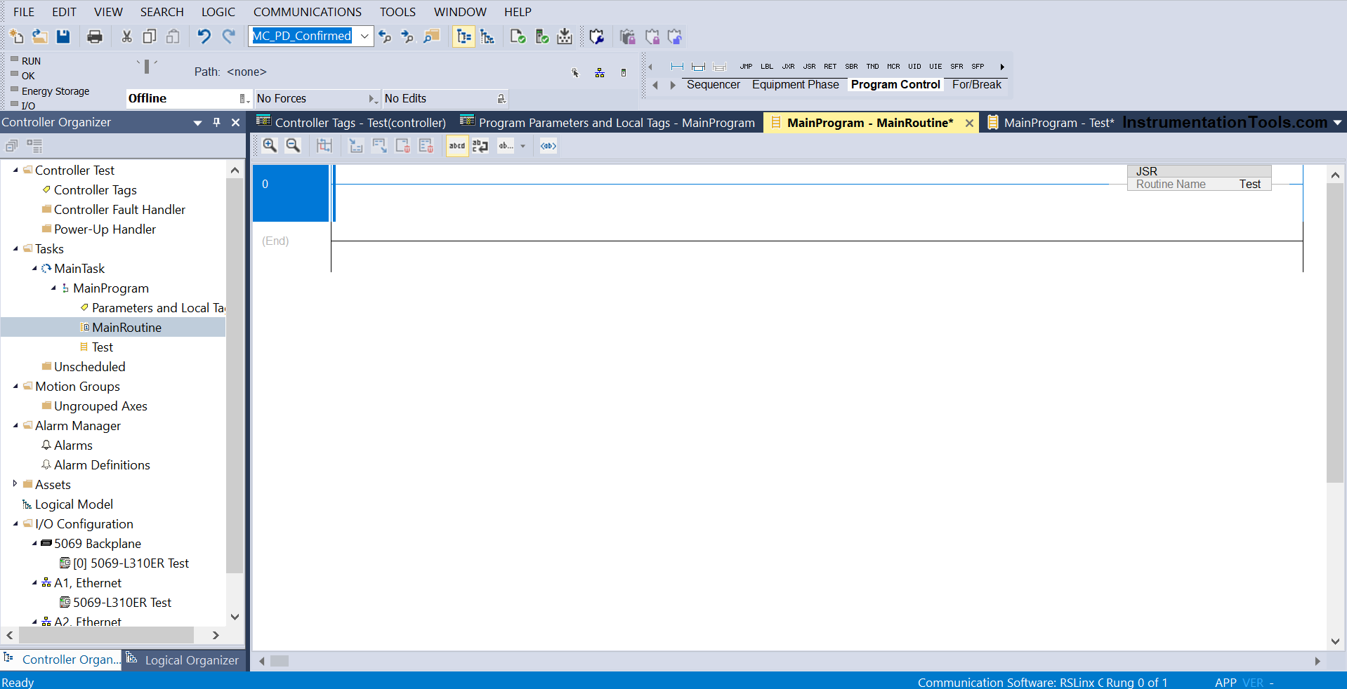
Refer to the first image. The Rockwell PLC software supports the following four languages – ladder logic, structured text, functional block diagram and sequential flow chart. In their language, it is called routine. You can add the routines in the program as highlighted.
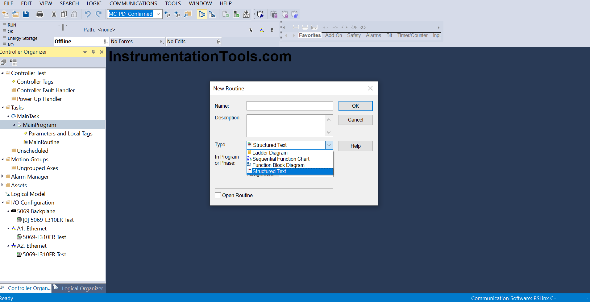
You can add as many programs as you want. If you see the flow, a program too is added in a task. Here too, you can add as many tasks as you want.
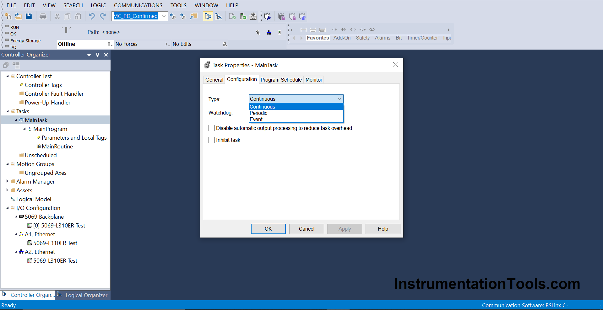
A task has the properties as shown in the second image, which is common in all the PLC’s. So, the flow goes like – task has a program and program has a routine.
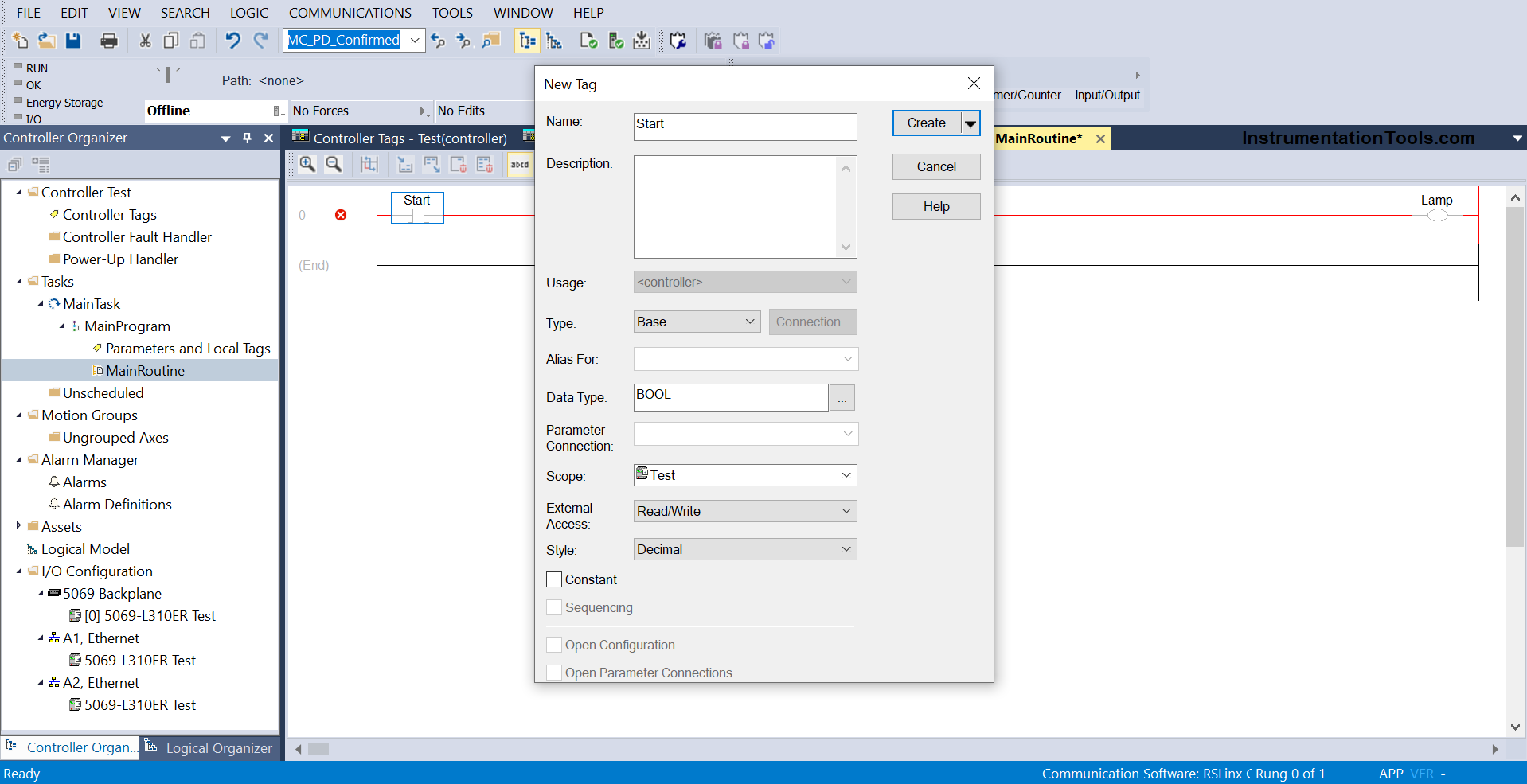
In a routine, once you start developing tags, you will need to define them. Right-click the tag to define a new one and you will find the following properties.
Here, you have to define its data type and other properties. You can then view the tags created in the controller tags section as shown on the left-hand side of the control bar.
Then, you need to add the section we created in task configuration through an instruction called JSR (jump to subroutine). It is used for calling the routine you created and executing it during processing runtime.
If a particular routine is not added in JSR, then it will not execute.
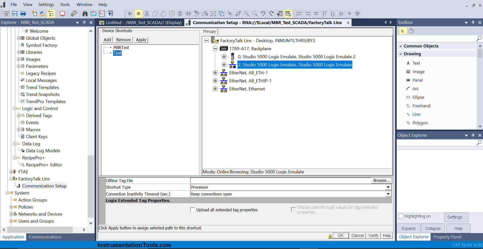
Now, we head on to the graphics part. In Rockwell automation, one thing to remember is that you first need to create a path in software called RSLinx Classic, which communicates between a PLC program and an HMI program. Refer to this article for more details.
Now, we created a path called Test as shown in the figure below, and assigned the corresponding path. This is the path which will communicate between the PLC program and HMI program. It is very necessary to do this, otherwise the tags will not reflect the values in HMI graphics.
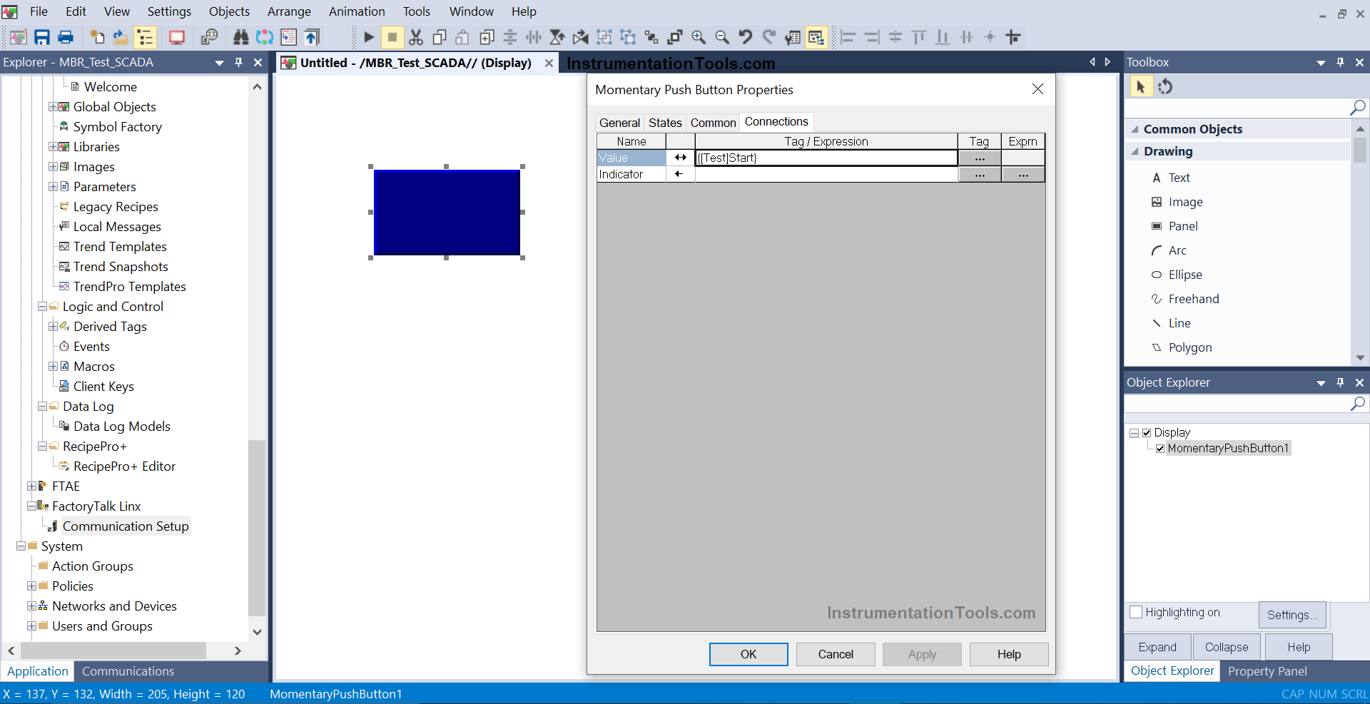
Now, take a screen and place a push button on it as shown in figure below. The button will have the properties as shown. Here, you have to link the tag of your PLC program with the path you defined in FactoryTalk Linx path.
Accordingly, you can design your screens and link the variables of your PLC program. But, remember that the path must be correct.
If you liked this article, then please subscribe to our YouTube Channel for Instrumentation, Electrical, PLC, and SCADA video tutorials.
You can also follow us on Facebook and Twitter to receive daily updates.
Read Next:
- Configure Analog Input Devices in Studio 5000
- Create Templates in FactoryTalk View Studio
- PlantPAx Add-On Instructions in Studio 5000
- Create Faceplate in FactoryTalk View Studio
- Configuration of Control Valve in Studio 5000