This is a PLC Program to control the level of parallel tanks. Learn the PLC programming using this example.
Parallel Tanks Level Control
Problem Description
Two tanks are connected in parallel connection. We need to heat and cool the incoming material into the tanks and simultaneously control the level of the tanks.
Implement the PLC program for this application.
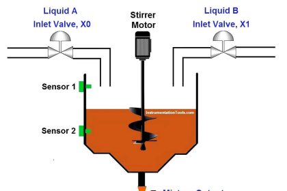
Problem Diagram

Problem Solution
Heating process is used to heat the material in the tank and cooling process is used to cool the material. Here consider both material are same as show in figure, inlet valve feeds material in both the tanks.
Here we can use level switches for detecting the low levels and high levels for both the tanks.
Use two temperature sensors for measuring the temperature of both the tanks.
Outlet valves are used at the bottom of the tanks to drain the materials for further process.
We will write PLC program for this application.
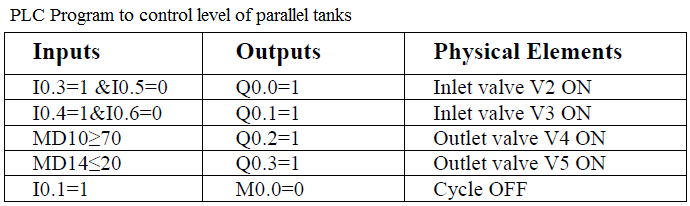
List of Inputs & Outputs
Digital Inputs
- Cycle START :- I0.0
- Cycle STOP :- I0.1
- Low level tank 1(LL1) :- I0.3
- Low level tank 2(LL2) :- I0.4
- High level tank 1(LH1) :- I0.5
- High level tank 2(LH2) :- I0.6
Digital Outputs
- Inlet valve V2 for heating tank :- Q0.0
- Inlet valve V3 for cooling tank :- Q0.1
- Outlet valve V4 for heating tank :- Q0.2
- Outlet valve V5 for cooling tank :- Q0.3
M memory
- Cycle ON bit :- M0.0
- Register for temperature of heating tank :- MD10
- Register for temperature of cooling tank :- MD14
- Outlet valve V5 for cooling tank :- Q0.3
PLC Program for level control of parallel tanks
Program Explanation
For this application we used S7-300 PLC and TIA portal software for programming. We can implement this logic by using other PLC also.
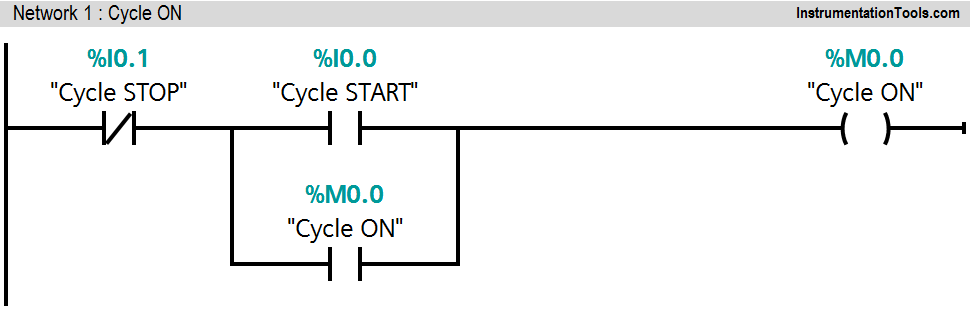
Network 1:
This Network is for latching circuit. Whenever START button is pressed (I0.0), Cycle ON (M0.0) bit will be ON. Cycle can be STOP by pressing STOP PB (I0.1).
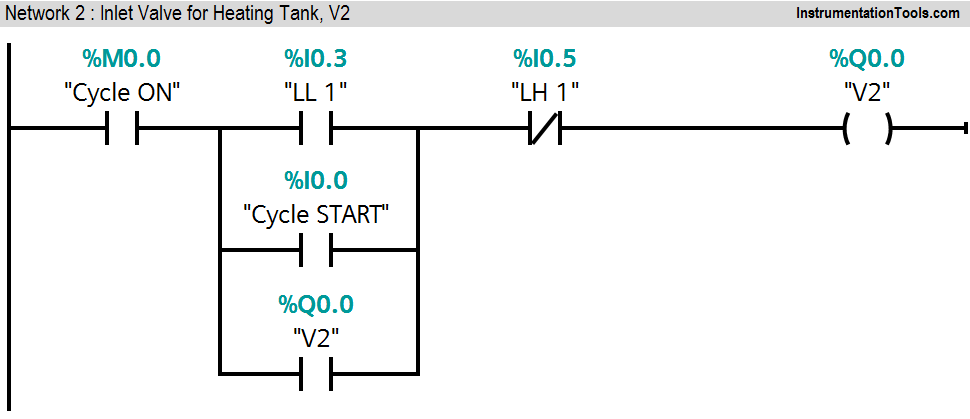
Network 2:
When heating tank level low (I0.3) is detected, inlet valve V2 (Q0.0) will be ON. If level high of tank 1(I0.5) is not detected and START (I0.0) button is pressed, inlet valve V2 (Q0.0) will be ON.
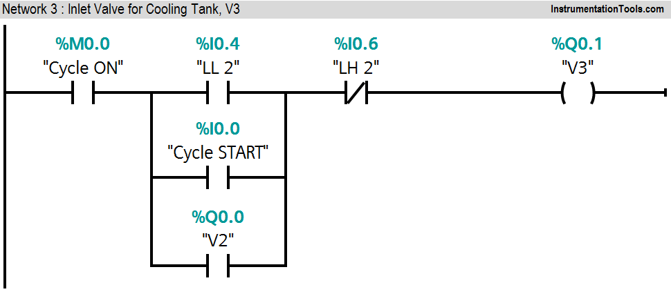
Network 3:
If level low of tank 2 (I0.4) is detected, inlet valve V3 (Q0.1) will be ON. If START button is pressed and high level of tank 2 (I0.6) is not detected, inlet valve V3 (Q0.1) will be ON.
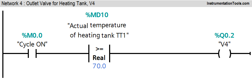
Network 4:
If cycle is ON and actual temperature of heating tank (MD10) is greater or equal than set temperature (70°C), outlet valve V4 (Q0.2) will be ON
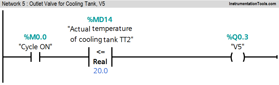
Network 5:
If cycle is ON and actual temperature of cooling tank (MD14) is less or equal than set temperature (20°C), outlet valve V5 (Q0.3) will be ON.
Note :- This example is only for explanation purpose only. We can implement this logic in any PLC or using relay logic. Above application may be different from actual application or may be a part of the plant logic.
Result
Author: Bhavesh
If you liked this article, then please subscribe to our YouTube Channel for PLC and SCADA video tutorials.
You can also follow us on Facebook and Twitter to receive daily updates.
Read Next:
- Sequential Motor Control in PLC
- PLC Program using Logic GATE
- Alarm and Trip Documentation
- Data Comparison PLC Instructions
- What is a Seal-in Circuit?


Thank you again for your efforts exerted in promoting education.
i want same process in scada.
????????