Inst ToolsInst ToolsInst Tools
  • Courses
  • Automation
    • PLC
    • Control System
    • Safety System
    • Communication
    • Fire & Gas System
  • Instrumentation
    • Design
    • Pressure
    • Temperature
    • Flow
    • Level
    • Vibration
    • Analyzer
    • Control Valve
    • Switch
    • Calibration
    • Erection & Commissioning
  • Interview
    • Instrumentation
    • Electrical
    • Electronics
    • Practical
  • Q&A
    • Instrumentation
    • Control System
    • Electrical
    • Electronics
    • Analog Electronics
    • Digital Electronics
    • Power Electronics
    • Microprocessor
  • Request
Search
  • Books
  • Software
  • Projects
  • Process
  • Tools
  • Basics
  • Formula
  • Power Plant
  • Root Cause Analysis
  • Electrical Basics
  • Animation
  • Standards
  • 4-20 mA Course
  • Siemens PLC Course
Reading: ControlLogix Architecture – Rockwell Automation
Share
Font ResizerAa
Inst ToolsInst Tools
Font ResizerAa
  • Courses
  • Design
  • PLC
  • Interview
  • Control System
Search
  • Courses
  • Automation
    • PLC
    • Control System
    • Safety System
    • Communication
    • Fire & Gas System
  • Instrumentation
    • Design
    • Pressure
    • Temperature
    • Flow
    • Level
    • Vibration
    • Analyzer
    • Control Valve
    • Switch
    • Calibration
    • Erection & Commissioning
  • Interview
    • Instrumentation
    • Electrical
    • Electronics
    • Practical
  • Q&A
    • Instrumentation
    • Control System
    • Electrical
    • Electronics
    • Analog Electronics
    • Digital Electronics
    • Power Electronics
    • Microprocessor
  • Request
Follow US
All rights reserved. Reproduction in whole or in part without written permission is prohibited.
Inst Tools > Blog > PLC Tutorials > ControlLogix Architecture – Rockwell Automation

ControlLogix Architecture – Rockwell Automation

Today we will discuss ControlLogix architecture and components of Allen Bradley PLC of Rockwell Automation.

Last updated: May 3, 2023 9:54 am
vicky
PLC Tutorials
No Comments
Share
5 Min Read
SHARE

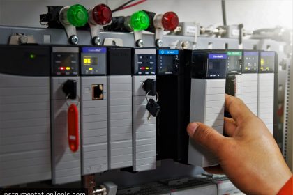
In the last article, we discussed the most common type of PLC used in large-scale industries i.e. AB PLC (1756 ControlLogix).

ControlLogix Architecture

Today we will discuss about its architecture.

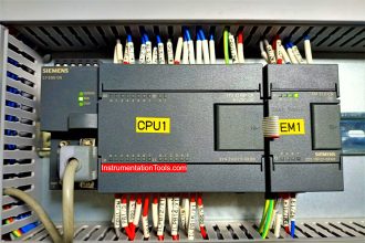
As seen in the picture, the control system consists of power supply modules, communication module, controller (1756-L55xx), redundancy module, ControlNet communication modules (1756-CNBR), remote IO modules & some other modules like flex IO & AC drive module.

ControlLogix Architecture - Rockwell Automation

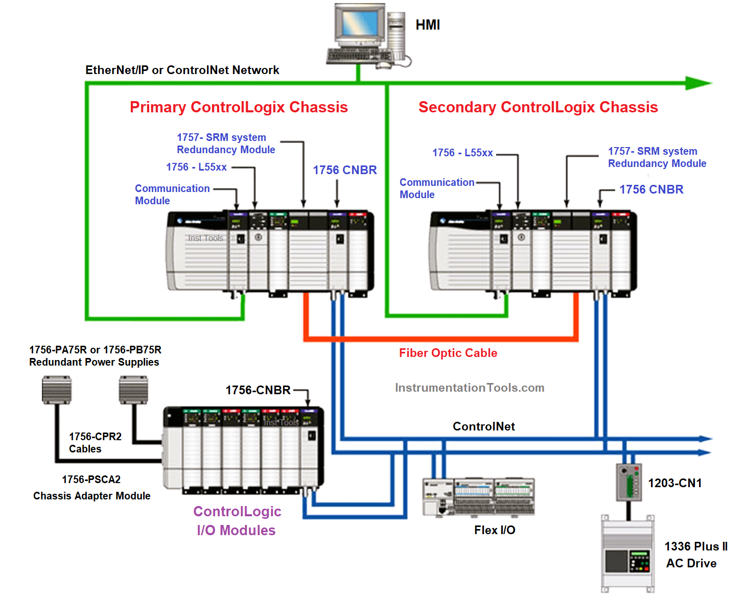
As we are aware that a system has 2 controllers and the system we are talking about here also has 2 controllers installed in 2 different chassis. In the above picture, you can find the primary and secondary ControlLogix chassis.

The controller (CPU) can be identified by a key slot given on it. The CPU has 3 different modes like RUN, REMOTE RUN & PROGRAM.

Redundancy can be established through redundancy modules installed in both chassis connected through Fiber Optic cable. It is shown in the red color line in the above picture.

Once the redundancy modules in the redundant chassis pair are connected and powered, they determine which chassis is the primary chassis and which is the secondary chassis.

There are two PLC systems, we can simply call them PLC A and PLC B, or, chassis A and chassis B. We can also call them the primary controller (PLC A) and secondary controller (PLC B).

Either primary controller or secondary controller will be active and online for monitoring and controlling the plant. The other controller will be in standby mode. The other controller will be active if there is a problem with the primary controller.

If a switchover occurs, the new primary controller continues to execute programs, which begin with the highest-priority task that had been executed on the previous primary controller. The PLC’s switchovers occur as fast as 20 ms.

As we have seen controllers in redundancy, we can place the same IO modules in both chassis to make them redundant too.

Now the system we have taken has IO installed in the remote chassis. So here a 1756-CNBR card is installed in the main chassis and remote IO chassis so that they can communicate.

A redundant type connection or single connection can be used as per requirement (Here redundant is used). Remote IO chassis has separate power modules.

Similarly, different modules like flex IO & AC drive modules can be connected using ControlNet.

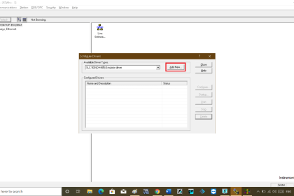
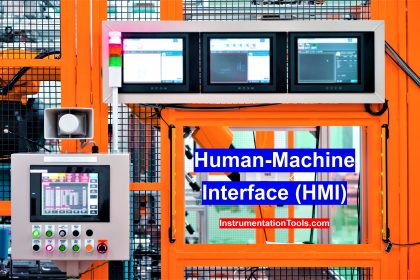
We can use Ethernet to communicate with server/HMI, although ControlNet can also be used. The advantage of Ethernet is high bandwidth i.e. 100 Mbps of 1 Gbps depending on the module used whereas ControlNet only gives 5 Mbps bandwidth.

Also, Ethernet is more preferred while having communication with other networks/systems. Other communication modes available are DeviceNet, DH+, DH485, Modbus & SynchLink.

The architecture we discussed is for a single controller used in a very small plant. But if the plant is big and has more areas then more controllers are required.

Also, a network of all controllers is also necessary to access them.

Network Gateway of Allen Bradley PLC

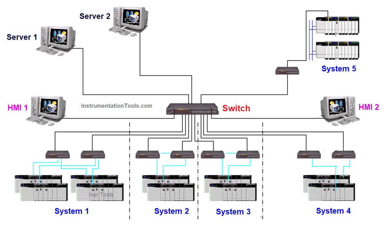
Now if the plant is large with many units in different physical areas and each having its own dedicated PLC, then the above-shown network can be made with the use of switches and Ethernet connection.

This was all about the architecture of AB PLC ControlLogix.

Hope you all enjoyed it.

If you liked this article, then please subscribe to our YouTube Channel for Instrumentation, Electrical, PLC, and SCADA video tutorials.

You can also follow us on Facebook and Twitter to receive daily updates.

Read Next:

  • Scan Cycle in SIEMENS PLC
  • Cloud-Based SCADA Projects
  • PLC-based Gas Detection System
  • Create New Project in Studio 5000
  • Rockwell Allen Bradley PLC Projects
Don't Miss Our Updates
Be the first to get exclusive content straight to your email.
We promise not to spam you. You can unsubscribe at any time.
Invalid email address
You've successfully subscribed !

Continue Reading

PLC Ladder Logic for Opposite Acting Control Valves Application
Toggle Switch & Sensor: Conveyor and Puncher PLC Program
PLC Program for Blinking Lamp on 5 Seconds Interval
Introduction to PLC Ladder Diagrams
ON Delay Timer using PLC
Most Asked Questions on SCADA with Answers
Share This Article
Facebook Whatsapp Whatsapp LinkedIn Copy Link
Share
Leave a Comment

Leave a Reply Cancel reply

Your email address will not be published. Required fields are marked *

Stay Connected

128.3kFollowersLike
69.1kFollowersFollow
210kSubscribersSubscribe
38kFollowersFollow

Categories

Explore More

PLC Program for Flow Totalizer
Timers in PLC Programming – Siemens Tia Portal Tutorials
Connecting Blocks in Functional Block Diagram – Studio 5000
What is the OPC Server?
Top 5 Advantages of Human-Machine Interface (HMI)
MCQ on PLC (Programmable Logic Controller)
PLC Program for 2 Push buttons to Control 1 Output
CRA Module in Schneider PLC – Remote IO Adapter Module

Keep Learning

Principle of Operation of PLC

Principle of Operation of PLC

Delta PLC Simulator

How to Work with Delta PLC Simulator?

Bit Shift Registers PLC Program

PLC Light Sequence Control using Bit Shift Registers

PLC Program for motor operation based on time cycle

PLC Motor Operation based on Time Cycle Sequence – Program

Site Commissioning Steps for PLC Programmers

Site Commissioning Steps for PLC Programmers

PLC Power Supply and Operating Voltages

PLC Power Supply and Operating Voltages

What is an Electromechanical Relay

Difference Between Solid State Relay and Electromechanical Relay

DCS Vs PLC

Difference between DCS & PLC Systems

Learn More

Vortex Flow Meter Animation

Basic Working Principle of Vortex Flowmeter

Monsoon Protection for Field Instruments and Junction Boxes

Monsoon Protection for Field Instruments and Junction Boxes

Modbus Network Motor Control

Motor Control using Modbus Communication and Hardwired Signals

Site Acceptance Test (SAT) of PLC System

PLC System Site Acceptance Test (SAT)

SIS Fault Tolerance

SIS Hardware Fault Tolerance – Methods to Overcome HFT issues

CAN Protocol with the OSI Model

Basics for CAN Bus Protocol – Controller Area Network

Stability in Frequency Domain

Feedback Compensation

HT motors Corrosion Problem

HT motors Corrosion Problem

Menu

  • About
  • Privacy Policy
  • Copyright

Quick Links

  • Learn PLC
  • Helping Hand
  • Part Time Job

YouTube Subscribe

Follow US
All rights reserved. Reproduction in whole or in part without written permission is prohibited.
Welcome Back!

Sign in to your account

Username or Email Address
Password

Lost your password?