Inst ToolsInst ToolsInst Tools
  • Courses
  • Automation
    • PLC
    • Control System
    • Safety System
    • Communication
    • Fire & Gas System
  • Instrumentation
    • Design
    • Pressure
    • Temperature
    • Flow
    • Level
    • Vibration
    • Analyzer
    • Control Valve
    • Switch
    • Calibration
    • Erection & Commissioning
  • Interview
    • Instrumentation
    • Electrical
    • Electronics
    • Practical
  • Q&A
    • Instrumentation
    • Control System
    • Electrical
    • Electronics
    • Analog Electronics
    • Digital Electronics
    • Power Electronics
    • Microprocessor
  • Request
Search
  • Books
  • Software
  • Projects
  • Process
  • Tools
  • Basics
  • Formula
  • Power Plant
  • Root Cause Analysis
  • Electrical Basics
  • Animation
  • Standards
  • 4-20 mA Course
  • Siemens PLC Course
Reading: Control Valve Failure Rate Calculation
Share
Font ResizerAa
Inst ToolsInst Tools
Font ResizerAa
  • Courses
  • Design
  • PLC
  • Interview
  • Control System
Search
  • Courses
  • Automation
    • PLC
    • Control System
    • Safety System
    • Communication
    • Fire & Gas System
  • Instrumentation
    • Design
    • Pressure
    • Temperature
    • Flow
    • Level
    • Vibration
    • Analyzer
    • Control Valve
    • Switch
    • Calibration
    • Erection & Commissioning
  • Interview
    • Instrumentation
    • Electrical
    • Electronics
    • Practical
  • Q&A
    • Instrumentation
    • Control System
    • Electrical
    • Electronics
    • Analog Electronics
    • Digital Electronics
    • Power Electronics
    • Microprocessor
  • Request
Follow US
All rights reserved. Reproduction in whole or in part without written permission is prohibited.
Inst Tools > Blog > Safety Instrumented System (SIS) > Control Valve Failure Rate Calculation

Control Valve Failure Rate Calculation

Last updated: March 22, 2019 10:50 am
Editorial Staff
Safety Instrumented System (SIS)
1 Comment
Share
3 Min Read
SHARE

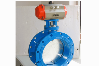
Suppose a control valve manufacturer produces a large number of valves, which are then sold to customers and used in comparable process applications.

After a period of 5 years, data is collected on the number of failures these valves experienced. Five years is well within the useful life of these control valves, so we know none of the failures will be due to wear-out, but rather to random causes.

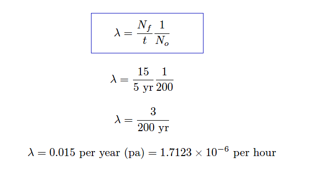
Supposing customers report an average of 15 failures for every 200 control valves in service over the 5-year period, calculate the failure rate (λ) and the MTTF for these control valves.

Control Valve Failure Rate Calculation

The testing scenario is one where failures are repaired in a short amount of time, since these are working valves being maintained in a real process environment. Thus, we may calculate lambda as a simple fraction of failed components to total components.

Using the appropriate formula, relating number of failed components to the total number of components:

Control Valve Failure Rate Calculation

With this value for lambda being so much larger than the microprocessor’s transistors, it is not necessary to use a unit such as FIT to conveniently represent it.

MTTF = 1/λ = 66.667 years = 584000 hours

Mean Time To Failure (MTTF) is the amount of time it would take to log a number of failures equal to the total number of valves in service, given the observed rate of failure due to random causes.

Note that MTTF is largely synonymous with MTBF. The only technical difference between MTBF and MTTF is that MTTF more specifically relates to situations where components are repairable, which is the scenario we have here with well-maintained control valves.

Note : The typically large values we see for MTBF and MTTF can be misleading, as they represent a theoretical time based on the failure rate seen over relatively short testing times where all components are “young.”

In reality, the wear-out time of a component will be less than its MTBF. In the case of these control valves, they would likely all “die” of old age and wear long before reaching an age of 66.667 years!
Articles You May Like :

SIS Logic Solver

Control Valve Animation

Partial Stroke Test Theory

Pressure Protection Devices

Safety Instrumented Function

Don't Miss Our Updates
Be the first to get exclusive content straight to your email.
We promise not to spam you. You can unsubscribe at any time.
Invalid email address
You've successfully subscribed !

Continue Reading

SIS Emergency Block Valves (EBV)
SIS Hardware Fault Tolerance – Methods to Overcome HFT issues
SIS Final Control Elements
SIS System Testing – Safety PLC
Over Pressure Protection Devices
Safety Instrumented System Handbook – SIS Tutorials
Share This Article
Facebook Whatsapp Whatsapp LinkedIn Copy Link
Share
1 Comment
  • Farooq says:
    March 13, 2018 at 7:00 am

    What is mttf and mtbf

    Reply

Leave a Reply Cancel reply

Your email address will not be published. Required fields are marked *

Stay Connected

128.3kFollowersLike
69.1kFollowersFollow
210kSubscribersSubscribe
38kFollowersFollow

Categories

Explore More

Transmitter Proof Testing
SIS Sensors
SIS Design – Safety Instrumented System
Partial Stroke Testing Device (PSD) in SIS Final Control Element
SIS Instrument Sharing – Transmitters Shared for BPCS and SIS Example
SIS Safety Requirements
Automated Block Valve (ABV)
Process Safety and Instrumentation

Keep Learning

Probability of failure on demand (PFD)

Probability of Failure on Demand (PFD)

safety control system

Safety Instrumented Burner Management System

Safety Integrity Level (SIL)

BPCS Control System and ESD Safety System of Delta-V DCS

BPCS Control System and ESD Safety System of Delta-V DCS

Basic Terms used in SIL Verification

Basic Terms used in SIL Verification

purge air blower

SIS – Safety Instrumented System Example

Selecting a SIS or SIL Level

Importance of Safety Integrity Level

safety PLC programming

SIS Logic Solver

Learn More

Power Electronics Objective Questions

PWM Inverter Quiz

Power Outlet

How does Electrical Power Outlet Work?

control-valves-classification

Types of Control Valves

What is a Magnetic Contactor

What is a Magnetic Contactor? – Principle, Types, Advantages

Power Systems Questions & Answers

Power Systems MCQ Series 1

why-reactive-power-is-generated-at-load

Why Reactive Power is Generated at Load

Pneumatic Cylinder Air Flow Calculation

Pneumatic Cylinder Air Flow Calculation

Intelligent MCC

What is Smart or Intelligent MCC?

Menu

  • About
  • Privacy Policy
  • Copyright

Quick Links

  • Learn PLC
  • Helping Hand
  • Part Time Job

YouTube Subscribe

Follow US
All rights reserved. Reproduction in whole or in part without written permission is prohibited.
Welcome Back!

Sign in to your account

Username or Email Address
Password

Lost your password?