One “classic” example of an industrial automatic shutdown system is a Burner Management System (or BMS) designed to monitor the operation of a combustion burner and shut off the fuel supply in the event of a dangerous condition.
Sometimes referred to as flame safety systems, these systems watch for such potentially dangerous conditions as low fuel pressure, high fuel pressure, and loss of flame.
Other dangerous conditions related to the process being heated (such as low water level for a steam boiler) may be included as additional trip conditions.
Safety Instrumented BMS
The safety shutdown action of a burner management system is to halt the flow of fuel to the burner in the event of any hazardous detected condition.
The final control element is therefore one or more shutoff valves (and sometimes a vent valve in addition) to positively stop fuel flow to the burner.
Flame Sensor
A typical ultraviolet flame sensor appears in this photograph:

This flame sensor is sensitive to ultraviolet light only, not to visible or infrared light.
The reason for this specific sensitivity is to ensure the sensor will not be “fooled” by the visible or infrared glow of hot surfaces inside the firebox if ever the flame goes out unexpectedly.
Since ultraviolet light is emitted only by an active gas-fueled flame, the sensor acts as a true flame detector, and not a heat detector.
Safety Shut-off Valve
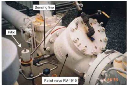
One of the more popular models of fuel gas safety shutoff valve used in the United States for burner management systems is shown here, manufactured by Maxon:

This particular model of shutoff valve has a viewing window on it where a metal tag linked to the valve mechanism marked “Open” (in red) or “Shut” (in black) positively indicates the valve’s mechanical status.
Like most safety shutoff valves on burner systems, this valve is electrically actuated, and will automatically close by spring tension in the event of a power loss.
Another safety shutoff valve, this one manufactured by ITT, is shown here:

Close inspection of the nameplate on this ITT safety valve reveals several important details. Like the Maxon safety valve, it is electrically actuated, with a “holding” current indicated as 0.14 amps at 120 volts AC.
Inside the valve is an “auxiliary” switch designed to actuate when the valve has mechanically reached the full “open” position.
An additional switch, labeled valve seal overtravel interlock, indicates when the valve has securely reached the full “shut” position.
This “valve seal” switch generates a proof of closure signal used in burner management systems to verify a safe shutdown condition of the fuel line.
Both switches are rated to carry 15 amps of current at 120 VAC, which is important when designing the electrical details of the system to ensure the switch will not be tasked with too much current.
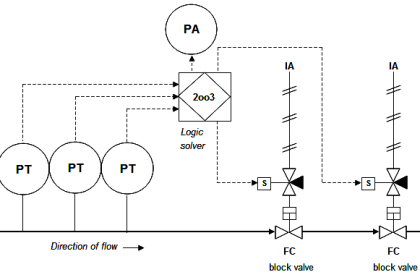
BMS P&ID
A simple P&ID for a gas-fired combustion burner system is shown here. The piping and valving shown is typical for a single burner.
Multiple-burner systems are often equipped with individual shutoff valve manifolds and individual fuel pressure limit switches.
Each burner, if multiple exist in the same furnace, must be equipped with its own flame sensor:

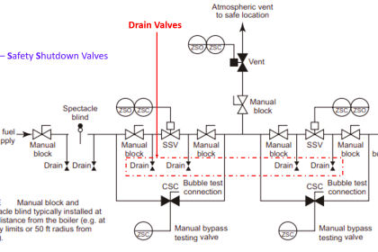
Note the use of double-block and bleed shutdown valves to positively isolate the fuel gas supply from the burner in the event of an emergency shutdown.
The two block valves are specially designed for the purpose (such as the Maxon and ITT safety valves previously shown), while the bleed valve is often nothing more than an ordinary electric solenoid valve.
Most burner management systems are charged with a dual role: both to manage the safe shutdown of a burner in the event of a hazardous condition, and the safe start-up of a burner in normal conditions.
Start-up of a large industrial burner system usually includes a lengthy purge time prior to ignition where the combustion air damper is left wide-open and the blower running for several minutes to positively purge the firebox of any residual fuel vapors.
After the purge time, the burner management system will ignite the burner (or sometimes ignite a smaller burner called the pilot, which in turn will light the main burner).
A burner management system executes all these pre-ignition and timing functions to ensure the burners will ignite safely and without incident.
While many industrial burners are managed by electromechanical relay or analog electronic control systems, the modern trend is toward microprocessor-based digital electronic controls.
One popular system is the Honeywell 7800 series burner control system, an example of which is shown in this photograph:

Microprocessor controls provide numerous advantages over relay-based and analog electronic burner management systems.
Timing of purge cycles is far more accurate with microprocessor control, and the requisite purge time is more difficult to override.
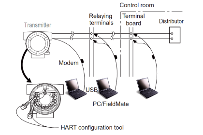
Microprocessor-based burner controls usually have digital networking capability as well, allowing the connection of multiple controls to a single computer for remote monitoring.
The Honeywell 7800 series additionally offers local “annunciator” modules to visually indicate the status of permissive (interlock) contacts, showing maintenance personnel which switches are closed and what state the burner control system is in:

The entire “gas train” piping system for a dual-fuel boiler at a wastewater treatment facility appears in the following photograph.
Note the use of double-block and bleed valves on both “trains” (one for utility-supplied natural gas and the other for “sludge gas” produced by the facility’s anaerobic digesters), the block valves for each train happening to be of different manufacture.
A Honeywell 7800 flame safety control system is located in the blue enclosure: