Inst ToolsInst ToolsInst Tools
  • Courses
  • Automation
    • PLC
    • Control System
    • Safety System
    • Communication
    • Fire & Gas System
  • Instrumentation
    • Design
    • Pressure
    • Temperature
    • Flow
    • Level
    • Vibration
    • Analyzer
    • Control Valve
    • Switch
    • Calibration
    • Erection & Commissioning
  • Interview
    • Instrumentation
    • Electrical
    • Electronics
    • Practical
  • Q&A
    • Instrumentation
    • Control System
    • Electrical
    • Electronics
    • Analog Electronics
    • Digital Electronics
    • Power Electronics
    • Microprocessor
Search
  • Books
  • Software
  • Projects
  • Process
  • Tools
  • Basics
  • Formula
  • Power Plant
  • Root Cause Analysis
  • Electrical Basics
  • Animation
  • Standards
  • 4-20 mA Course
  • Siemens PLC Course
Reading: Conductivity Analyzer Common Problems and Troubleshooting Tips
Share
Notification Show More
Font ResizerAa
Inst ToolsInst Tools
Font ResizerAa
  • Courses
  • Design
  • PLC
  • Interview
  • Control System
Search
  • Courses
  • Automation
    • PLC
    • Control System
    • Safety System
    • Communication
    • Fire & Gas System
  • Instrumentation
    • Design
    • Pressure
    • Temperature
    • Flow
    • Level
    • Vibration
    • Analyzer
    • Control Valve
    • Switch
    • Calibration
    • Erection & Commissioning
  • Interview
    • Instrumentation
    • Electrical
    • Electronics
    • Practical
  • Q&A
    • Instrumentation
    • Control System
    • Electrical
    • Electronics
    • Analog Electronics
    • Digital Electronics
    • Power Electronics
    • Microprocessor
Follow US
All rights reserved. Reproduction in whole or in part without written permission is prohibited.
Inst Tools > Blog > Analyzers > Conductivity Analyzer Common Problems and Troubleshooting Tips

Conductivity Analyzer Common Problems and Troubleshooting Tips

Many times conductivity analyzer malfunctions and learn troubleshooting tips to solve the common problems with solutions.

Last updated: August 1, 2022 8:52 am
Editorial Staff
Analyzers
No Comments
Share
5 Min Read
SHARE

Conductivity measurement is used in various plants for measuring the conductivity of various fluids.

Many times Conductivity analyzer malfunctions and troubleshooting the issue becomes necessary. Let us learn the troubleshooting guidelines for the Conductivity analyzer to solve the common problems.

Conductivity Analyzer Common Problems
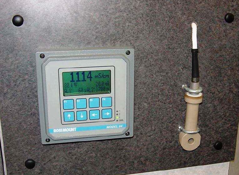
toroidal conductivity probe principle

Follow the below-mentioned steps for troubleshooting the Conductivity analyzer. 

  1. The first step is to check whether the Conductivity analyzer is in power ON condition or not. If the display is found in off condition, then check the voltage supply to the conductivity transmitter. If voltage is not present, then check the fuse/barrier in marshalling cabinet. If the fuse is blown, then replace the blown fuse with a fuse of the same rating. If the fuse is ok, then check all the intermediate cable connection tightness. If found ok, then check the cable healthiness. Replace the cable pair if the cable is not ok.
  2. If the voltage is ok, then the power card might be having the issue. Replace the power card with the same type of power card if the power card is removable. If the power card is not replaceable, then replace the conductivity transmitter.
  3. Now check the process sample coming to the conductivity analyzer. Verify the drain tube. A steady and bubble-free sample should be coming out of the sample tube. If no sample is coming, then check the isolation valve. The isolation valve might be in close condition. Open the isolation valve after verifying the tubing condition.
  4. Check the sample flow coming out through the drain line. The sample flow should be laminar. There should be no bubbles coming out with the sample fluid. Adjust the flow as per the requirement of the conductivity sensor. Sample flow can be confirmed from the vendor manual of the conductivity sensor.
  5. Remove the conductivity sensor and check the physical condition of the conductivity sensor. There should be no deposition on the conductivity sensor. If any foreign deposition is found, then clean the conductivity sensor. Use lint-free paper or smooth cloth so the sensor does not get damaged.
  6. Check the condition of the flow cell also in which the conductivity analyzer is installed. If found any issue like blockage of external material deposition, then attend to the issue.
  7. If still reading is not satisfactory, then check the conductivity analyzer’s value in the atmosphere. The value should be zero and stable. If the value is not zero then clean the conductivity sensor again. If the conductivity value is not coming to zero, then do zero calibration.
  8. Now check the value of the conductivity analyzer in some standard solution. If the conductivity analyzer is not showing proper value then do span calibration.
  9. If the Conductivity analyzer is not showing proper value, then check the inbuilt RTD’s healthiness. Wiring details are to be confirmed as per the vendor manual. If RTD is not responding properly, then put the temperature in manual mode and set the process fluid’s temperature. You can expect some error in measurement with manual mode. If the process temperature is quickly changing, then do not put the temperature in manual mode. Replace the conductivity sensor.
  10. Check the value of the cell constant of the conductivity sensor. The incorrect cell constant can also give incorrect readings.
  11. If the value in the field display and the control system do not match, then check both configured ranges. Ranges should be as per the datasheet or any other approved document and must be the same.
  12. If output values are different than the display values in the field, then replace the communication card, if replaceable. If the communication card is not replaceable, then replace the conductivity transmitter. Communication card failure is also possible and in many cases, this is the reason for the mismatch between the field and system values.
  13. If the reading is fluctuating more, then increase the time constant by a few seconds.
Don't Miss Our Updates
Be the first to get exclusive content straight to your email.
We promise not to spam you. You can unsubscribe at any time.
Invalid email address
You've successfully subscribed !

Continue Reading

Ammonia Analyzer Principle
Dissolved Oxygen Analyzer Interview Questions & Answers
Ionization chamber Principle
Thermal Conductivity Detector (TCD) Principle
Tunable Diode Laser Analyzer Working Principle
Calibration and Troubleshooting of Oxygen Analyzer
Share This Article
Facebook Whatsapp Whatsapp LinkedIn Copy Link
Share
Leave a Comment

Leave a Reply Cancel reply

Your email address will not be published. Required fields are marked *

Stay Connected

128.3kFollowersLike
69.1kFollowersFollow
208kSubscribersSubscribe
38kFollowersFollow

Categories

Explore More

Dual-beam Non-dispersive Analyzer
pH Analyzer Interview Questions and Answers
Difference Between Absolute and Relative Humidity
What is Infrared Flue Gas Analyzer? – Working Principle
Measurement of Carbon Dioxide in Flue Gas
H2S Measurement Using Lead Acetate Principle
Various Types of Sensors used in Water Treatment Plant
Basics of ORP Measurement

Keep Learning

mass spectrometer sample system

Mass Spectrometer Working Principle

Chemiluminescent Analyzer

Chemiluminescence

Oil in Water Analyzer Principle

Oil in Water Analyzer Working Principle

Moisture and Dew Point Analyzer Problems

Moisture and Dew Point Analyzer Problems and Troubleshooting Tips

CEMS Classification

CEMS Principle, Types, Advantages, and Disadvantages

thin-layer chromatography

Thin-Layer Chromatography : Manual Method

Technologies for Oxygen Gas Measurement

Technologies for Oxygen Gas Measurement

TOC Analyzer Principle

Total Organic Carbon Analyzer Principle

Learn More

7 Investments for Single Mothers

7 Investments for Single Mothers

port-guided globe valve plug

What is Port-guided Globe Valve ?

Pressure Temperature Compensation Flow Measurement

Pressure Temperature Compensation Flow Measurement

Allen-Bradley MicroLogix PLC Wiring

Programmable Logic Controller (PLC) Questions and Answers – 8

Arc Fault Breaker (AFB) Electrical Problem Solved

Arc Fault Breaker (AFB) Electrical Problem Solved

Flammable Gases and Vapors Class 1 & Class 2

Gas Detectors Standards

Why Using VoIP Systems

Why Using VoIP Systems Can Save You and Your Business Money?

Power Systems Questions & Answers

Power Systems MCQ Series 10

Follow US
All rights reserved. Reproduction in whole or in part without written permission is prohibited.
Welcome Back!

Sign in to your account

Username or Email Address
Password

Lost your password?