Today in this article, you will learn about the centrifugal compressor start permissive and interlocks used in the DCS and PLC automation systems.
Compressors are installed in every industry. Without compressors, an industry cannot run because Instrument Air, Nitrogen, and Plant Air are obtained from Air Compressors only. In other gas plants also, compressors play a very important role in increasing the pressure of gases.
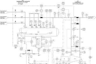
A compressor has a lube oil system for proper control and lubrication of the gearbox and bearings. A seal gas system is used to provide isolation between the process gas to be compressed and the oil system.
Centrifugal Compressor Start Permissive
Important Start Permissive in Centrifugal Compressor:
1) Most important permissive for starting the compressor is the seal gas pressure permissive. A minimum seal gas pressure is required for starting the lube oil system.
2) Lube oil supply pressure to the gearbox should be greater than some defined pressure. For this auxiliary lube oil pumps (AOP) are running in auto mode to keep this pressure steady.
Two lube oil pumps are present in any lube oil system of a centrifugal compressor. If one pump cannot build sufficient pressure, then the other pump starts automatically.
When the compressor is running, the main oil pump (MOP) runs which is engaged with the gearbox. This pump maintains the lube oil pressure. When the compressor is running, the auxiliary oil pumps will be stopped automatically after some time delay.
3) Lube oil supply temperature to gearbox should be maintained in the defined range. Example temperature should be above 30 degrees centigrade and below 65 degrees Centigrade.
3) No trip signal from Machine Condition Monitoring System (MCMS). Generally, a contact is taken from the MCMS system for tripping the compressor on high vibration or high temperature of the motor winding. All should be healthy.
4) Inlet Guide Vane (IGV) should have a minimum opening (usually 3%-5% open) and Anti surge valve (ASV)/ Blow Off Valve (BOV) should be fully open
5) We can give a limited number of start commands to the main motor in a fixed time interval.
For example, Say we have given the start command to the main motor, and due to some problem the main motor got tripped immediately. Now you can give second start command after some time delay only. This time delay is maybe 5 minutes, 15 minutes, 30 minutes, 60 minutes, etc. The time delay will depend on your motor parameters or as per your control philosophy. This is for the protection of the motor.
6) Low suction pressure also won’t allow the Compressor to start in case of a booster Compressor like HP Air Compressor.
7) Inter-cooler and after-cooler levels should not be high
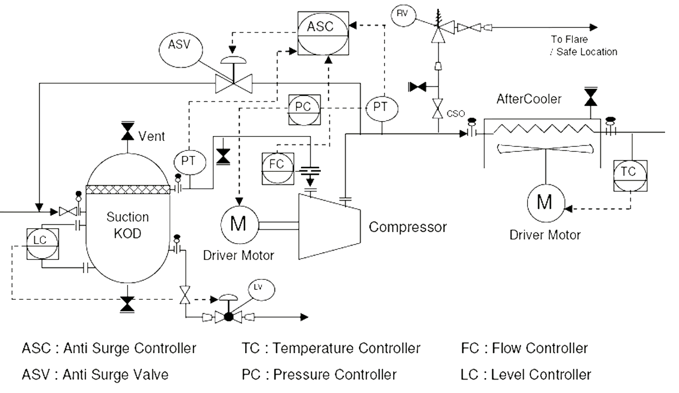
Centrifugal Compressor Interlocks
Important Interlocks in Centrifugal Compressor
1) Tripping on low seal gas pressure
2) Tripping on high vibration
3) Tripping on low lube oil pressure
4) Tripping on high lube oil temperature
5) Compressor unload on high motor current
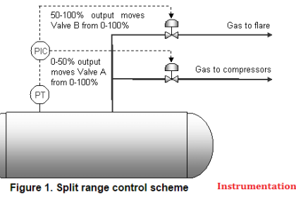
6) On high discharge pressure, IGV starts closing. If still high, discharge pressure doesn’t come down, then ASV/BOV starts opening.
7) Tripping on low suction pressure
8) Tripping on individual stage inlet temperature high
9) Tripping on high condensate level in inter cooler and after cooler. A level switch is installed in the inter-coolers and after-coolers.
10) Tripping due to surging (surging is calculated typically using parameters like pressure, temperature, and flow. Sometimes motor current is also taken for calculating the surging)