Inst ToolsInst ToolsInst Tools
  • Courses
  • Automation
    • PLC
    • Control System
    • Safety System
    • Communication
    • Fire & Gas System
  • Instrumentation
    • Design
    • Pressure
    • Temperature
    • Flow
    • Level
    • Vibration
    • Analyzer
    • Control Valve
    • Switch
    • Calibration
    • Erection & Commissioning
  • Interview
    • Instrumentation
    • Electrical
    • Electronics
    • Practical
  • Q&A
    • Instrumentation
    • Control System
    • Electrical
    • Electronics
    • Analog Electronics
    • Digital Electronics
    • Power Electronics
    • Microprocessor
  • Request
Search
  • Books
  • Software
  • Projects
  • Process
  • Tools
  • Basics
  • Formula
  • Power Plant
  • Root Cause Analysis
  • Electrical Basics
  • Animation
  • Standards
  • 4-20 mA Course
  • Siemens PLC Course
Reading: Selecting the Best Inductive or Capacitive Sensor
Share
Notification Show More
Font ResizerAa
Inst ToolsInst Tools
Font ResizerAa
  • Courses
  • Design
  • PLC
  • Interview
  • Control System
Search
  • Courses
  • Automation
    • PLC
    • Control System
    • Safety System
    • Communication
    • Fire & Gas System
  • Instrumentation
    • Design
    • Pressure
    • Temperature
    • Flow
    • Level
    • Vibration
    • Analyzer
    • Control Valve
    • Switch
    • Calibration
    • Erection & Commissioning
  • Interview
    • Instrumentation
    • Electrical
    • Electronics
    • Practical
  • Q&A
    • Instrumentation
    • Control System
    • Electrical
    • Electronics
    • Analog Electronics
    • Digital Electronics
    • Power Electronics
    • Microprocessor
  • Request
Follow US
All rights reserved. Reproduction in whole or in part without written permission is prohibited.
Inst Tools > Blog > Instrumentation Design > Selecting the Best Inductive or Capacitive Sensor

Selecting the Best Inductive or Capacitive Sensor

Last updated: October 4, 2017 9:26 am
Editorial Staff
Instrumentation Design
No Comments
Share
5 Min Read
SHARE

Hundreds of different proximity sensors are available for use in automation applications. There are several points to consider when you look for a sensor, as your choices could affect your application later down the road. Let’s take a look at why you would use an inductive or a capacitive sensor.

Selecting the Best Inductive or Capacitive Sensor

Inductive sensors

An inductive sensor is used to detect the presence of metals (such as steel, stainless steel, aluminum, or copper). An important factor to note is that our sensors have a different nominal sensing range depending on the material. The standard target is a mild steel plate that is 1 mm thick with square dimensions the size of the sensor.

Inductive sensors has a rated operating distance of 4 mm, but will pick up aluminum only at about 1.6 mm because of the 0.4 reduction factor for aluminum.

If a longer sensing range is needed, we also have reduction factor 1 sensors that do not have a reduction factor for steel , stainless steel, copper, and aluminum.

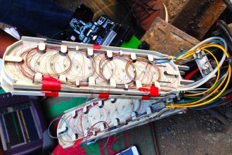
The common cylindrical inductives that we offer are 8 mm, 12 mm, 18 mm, and 30 mm. We do offer some smaller diameters as well such as 4 mm, 5 mm, and 6.5 mm models. Typically, a smaller diameter sensor has a higher switching frequency (number of times the sensors can change output states). This is an important feature to consider if the sensor will be used for a speed monitoring application involving a fast, rotating target. You can see an example in the image below.

select-inductive-capacitive-sensor
The environment in which the sensor is located in plays a role as well. Most of our inductive proximity sensors have an IP67 degree of protection. An IP67 rating means that the sensor can resist the ingress of dust and water such that the sensor stays sealed even if submerged in stagnant, low-depth water for short periods of time. If the sensor has to be used underwater continuously, it requires an IP68 degree of protection. For high-pressure washdown, an IP69K degree of protection is needed. These ratings are listed on the specification sheet.

Capacitive sensors

Capacitive sensors are capable of detecting plastic, wood, and other raw materials including metal. An inductive sensor can detect only metal. A common application is the detection of liquids, plastics, and grains. Capacitive liquid detection is used for level and presence detection.

Often times, this type of application involves sensing through a tube or tank to detect the liquid. Capacitive sensors have either a fixed sensitivity or an adjustable sensitivity. Depending on the material of the tube or sidewall, a capacitive can be selected to mount on the exterior of the tank/ tube and detect the fluid through the wall.

Factors would be the dielectric constant of the fluid and the material of the side wall. Tables with the dielectric constants of most materials can be found on the internet, or a brief list can be found in sensor catalog.

One typical application involves using a thin tube with a small capacitive wire tied to it to give an output when the fluid reaches the wire. This method of sensing can be useful in hydraulic cylinder applications.

Another popular solution utilizes our plastic sensor well that is drilled and fitted to the side of a tank. A cylindrical capacitive sensor can then be placed in this sensor well and used for level detection. This approach makes adjusting the sensitivity and removal of the sensor easy. Most cylindrical models have a potentiometer on the back for adjusting the sensitivity. Aside from the sensitivity adjustment and the ability to detect nonmetal targets, a capacitive sensor is similar to an inductive in most other aspects when considering housing size and range.

Also Read: How to Select an Actuator for Valve

Don't Miss Our Updates
Be the first to get exclusive content straight to your email.
We promise not to spam you. You can unsubscribe at any time.
Invalid email address
You've successfully subscribed !

Continue Reading

Pneumatic Signal Piping and Fittings
Redundant Power Supply for Critical Field Panels
Control Valve Recommended Practices for Harsh Process Conditions
What is Hammer Effect in Gauges ?
History of 3-15 psi, 10-50 mA, and 4-20 mA signals
Control Valve Selection Tips
Share This Article
Facebook Whatsapp Whatsapp LinkedIn Copy Link
Share
Leave a Comment

Leave a Reply Cancel reply

Your email address will not be published. Required fields are marked *

Stay Connected

128.3kFollowersLike
69.1kFollowersFollow
210kSubscribersSubscribe
38kFollowersFollow

Categories

Explore More

Basics of Fail-safe Circuits
Draw a ladder logic circuit for the electric motor of an air compressor ?
Why we use Cable Shielding with Ferrites ?
How to Select a Pressure Gauge
How to Calculate Heat Load in Electrical/Electronic Panel Enclosure
Industrial Automation Pre-Engineering Design Documents – Project & Process
Tagging Philosophy for Junction Box, Cable, and Cable Drum
Why is an Instrument Process Datasheet Required?

Keep Learning

Instrument Heat Trace

Electrical Heat Tracing

Solenoid Operated Valves and Latching Valves

Solenoid Operated Valves and Latching Valves

Instrument Air (IA) System

Process Design of Instrument Air System

on off valve actuator

How to Select an Actuator for Valve

Basic Requirements of Sizing the Control Valves

Basic Requirements of Control Valves Sizing

Loop Diagram

15 Loop Diagram Questions

Single Line Diagram of UPS System

UPS Selection Factors for a Control System

Instrument Control Package (ICP)

Package Control and Safety Systems Implementation Methods

Learn More

Digital Electronics Multiple Choice Questions

Controlled Inverter Objective Questions

Semi Conductor or Piezo Resistive Strain Gauge Principle

Semi Conductor or Piezo Resistive Strain Gauge Principle

Ethernet Questions and Answers

Ethernet Communication Interview Questions & Answers

Total Organic Carbon Analyzers Questions and Answers

Total Organic Carbon Analyzers Questions and Answers

Structured Text PLC Program for Measuring Event Duration

Structured Text PLC Program for Measuring Event Duration

Difference Between MPCB and MCCB

Difference Between MPCB and MCCB

Functional block diagram for analog alarms

PLC Logic for Analog Alarms using Functional Block Diagram

Types of Pressure

Basics of Pressure Measurement

Menu

  • About
  • Privacy Policy
  • Copyright

Quick Links

  • Learn PLC
  • Helping Hand
  • Part Time Job

YouTube Subscribe

Follow US
All rights reserved. Reproduction in whole or in part without written permission is prohibited.
Welcome Back!

Sign in to your account

Username or Email Address
Password

Lost your password?