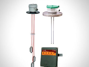
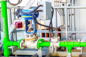
Level Troll working principle
An interesting design problem for displacement-type level transmitters is how to transfer the sensed weight of the displacer to the transmitter mechanism while positively sealing process vapor pressure from that same mechanism.
The most common solution to this problem is an ingenious mechanism called a torque tube. Unfortunately, torque tubes can be rather difficult to understand unless you have direct hands-on access to one, and so this section will explore the concept in more detail than is customarily available in reference manuals.
Imagine a solid, horizontal, metal rod with a flange at one end and a perpendicular lever at the other end. The flange is mounted to a stationary surface, and a weight suspended from the end of the lever.
A dashed-line circle shows where the rod is welded to the center of the flange:
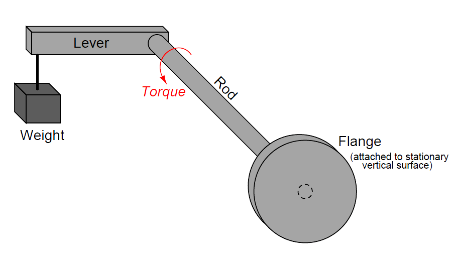
The downward force of the weight acting on the lever imparts a twisting force (torque) to the rod, causing it to slightly twist along its length.
The more weight hung at the end of the lever, the more the rod will twist. So long as the torque applied by the weight and lever never exceeds the elastic limit of the rod, the rod will continue to act as a spring.
If we know the “spring constant” of the rod, and measured its torsional deflection, we can in fact use this slight motion to measure the magnitude of the weight hung at the end of the lever.
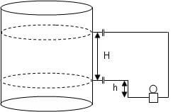
Applied to a displacer-type level instrument, a displacer takes the place of the weight at the lever’s end, the torsional deflection of this rod serving to indicate buoyant force.
As liquid rises, buoyant force on the displacer increases, making the displacer seem lighter from the rod’s perspective. The rod’s slight motion resulting from this apparent weight change, then, indicates liquid level.
Now imagine drilling a long hole through the rod, lengthwise, that almost reaches the end where the lever attaches. In other words, imagine a blind hole through the center of the rod, starting at the flange and ending just shy of the lever:
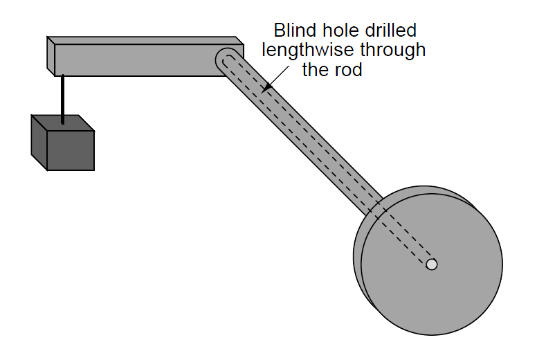
The presence of this long hole does not change much about the behavior of the assembly, except perhaps to alter the rod’s spring constant.
With less solid metal, the rod will be a weaker spring, and will twist to a greater degree with applied weight at the end of the lever. More importantly for the purpose of this discussion, though, the long hole transforms the rod into a tube with a sealed end.
Instead of a being a “torsion bar,” the rod is now more properly called a torque tube, twisting ever so slightly with applied weight at the end of the lever.
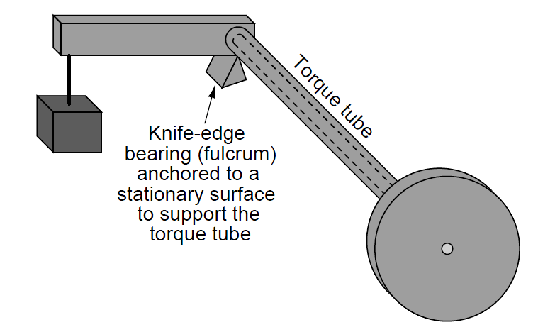
In order to give the torque tube vertical support so it does not sag downward with the applied weight, a supporting knife-edge bearing is often placed underneath the end of the lever where it attaches to the torque tube.
The purpose of this fulcrum is to provide vertical support for the weight while forming a virtually frictionless pivot point, ensuring the only stress applied to the torque tube is torque from the lever:
Finally, imagine another solid metal rod (slightly smaller diameter than the hole) spot-welded to the far end of the blind hole, extending out beyond the end of the flange:
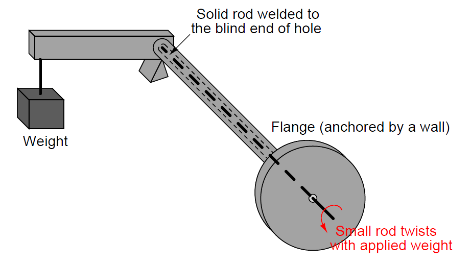
The purpose of this smaller-diameter rod is to transfer the twisting motion of the torque tube’s far end to a point past the flange where it may be sensed.
Imagine the flange anchored to a vertical wall, while a variable weight tugs downward at the end of the lever. The torque tube will flex in a twisting motion with the variable force, but now we are able to see just how much it twists by watching the rotation of the smaller rod on the near side of the wall.
The weight and lever may be completely hidden from our view by this wall, but the small rod’s twisting motion nevertheless reveals how much the torque tube yields to the force of the weight.
We may apply this torque tube mechanism to the task of measuring liquid level in a pressurized vessel by replacing the weight with a displacer, attaching the flange to a nozzle welded to the vessel, and aligning a motion-sensing device with the small rod end to measure its rotation.
As liquid level rises and falls, the apparent weight of the displacer varies, causing the torque tube to slightly twist. This slight twisting motion is then sensed at the end of the small rod, in an environment isolated from the process fluid pressure.
A photograph taken of a real torque tube from a Fisher “Level-Trol” level transmitter shows its external appearance:
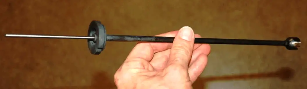
The dark-colored metal is the elastic steel used to suspend the weight by acting as a torsional spring, while the shiny portion is the inner rod used to transfer motion.
As you can see, the torque tube itself is not very wide in diameter. If it were, it would be far too stiff of a spring to be of practical use in a displacer-type level instrument, since the displacer is not typically very heavy, and the lever is not long.
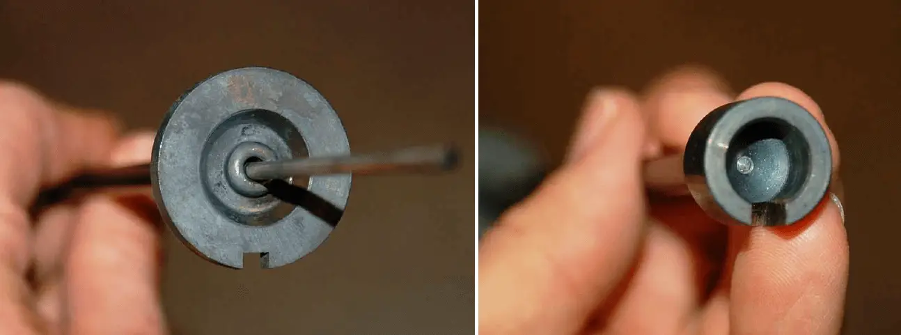
Looking closer at each end of the torque tube reveals the open end where the small-diameter rod protrudes (left) and the “blind” end of the tube where it attaches to the lever (right):
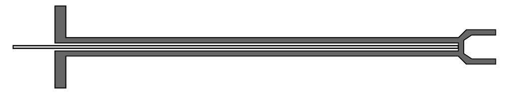
If we were to slice the torque tube assembly in half, lengthwise, its cross-section would look something like this:
This next illustration shows the torque tube as part of a whole displacement-style level transmitter :
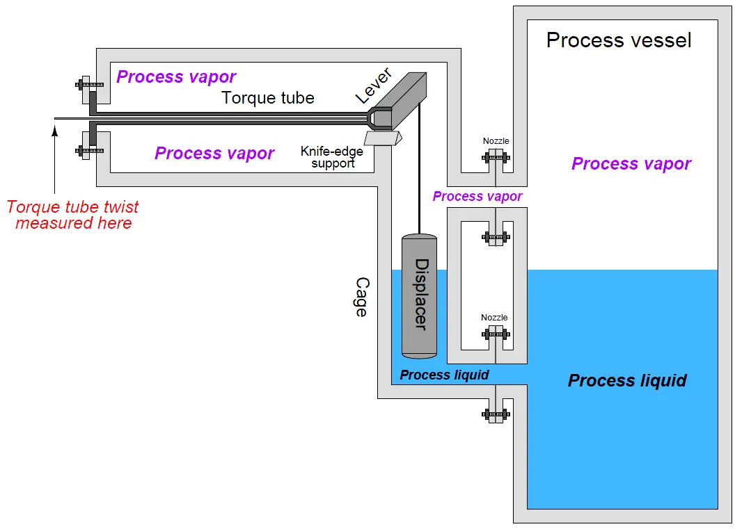
As you can see from this illustration, the torque tube serves three distinct purposes when applied to a displacer-type level measurement application:
(1) to serve as a torsional spring suspending the weight of the displacer,
(2) to seal off process fluid pressure from the position-sensing mechanism, and
(3) to transfer motion from the far end of the torque tube into the sensing mechanism.
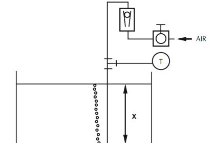
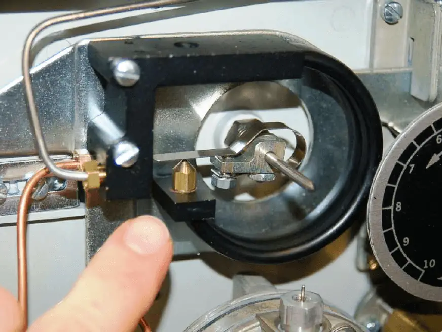
In pneumatic level transmitters, the sensing mechanism used to convert the torque tube’s twisting motion into a pneumatic (air pressure) signal is typically of the motion-balance design.
The Fisher Level-Trol mechanism, for example, uses a C-shaped bourdon tube with a nozzle at the end to follow a baffle attached to the small rod. The center of the bourdon tube is aligned with the center of the torque tube.
As the rod rotates, the baffle advances toward the nozzle at the bourdon tube tip, causing backpressure to rise, which in turn causes the bourdon tube to flex.
This flexing draws the nozzle away from the advancing baffle until a balanced condition exists. Rod motion is therefore balanced by bourdon tube motion, making this a motion-balance pneumatic system:
Note : Pneumatic based level transmitters are outdated and no more manufacturing or using in industries unless its have a very specific requirement.
Credits : Tony R. Kuphaldt – Creative Commons Attribution 4.0 License