HART is a digital signal that rides on a standard 4 mA … 20 mA process control loop. In the field of process automation, the 4 mA … 20 mA loop is very steady. You may hear of it being referred to as “quasi-static,” as it doesn’t change much. Field devices like mass flow, temperature, pressure transmitters, or valve positioners use this 4 mA … 20 mA signal. HART information is extra information that you get back from your field instruments.
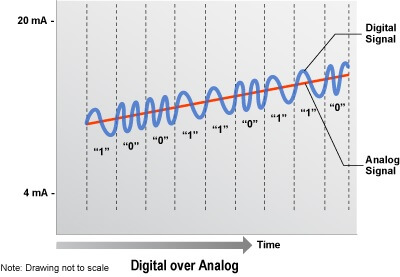
Historically, HART communication uses the BELL 202 telephone communication standard, which telephone land lines still use today. This standard was introduced in the early 1980s and uses Frequency Shift Keying (FSK) technology. FSK simply means that the information is keyed or coded into the frequency, which is how the data communicates back and forth. HART layers its digital communication signals on top of the 4 mA … 20 mA control signal.
A drawback based on today’s standards is the speed of HART communication, which is rather slow. HART is limited to 1200 bits/second and ranges from 1200 Hz to 2200 Hz. Information (1, 0) is represented by different frequencies. The HART signal creates 0s and 1s. A logic 1 is represented by 1200 Hz. A logic 0 is represented by 2200 Hz. On the plus side, HART communication doesn’t interrupt the 4 mA … 20 mA signal, and it allows a host application (master) to get up to three digital updates per second from a field device.
Back in the day when this technology was introduced, 1200 baud was screaming fast, but now it is painfully slow and just doesn’t measure up to our expectations. As an example, a LAN (Local Area Network), in common use today, perks along at 100 Mbits/second. That’s 1000 times faster than the BELL 202!
If the communication speeds are so slow, why do we continue to use HART communication for field instruments and devices? Well, the 4 mA … 20 mA control signals with FSK are reliable and have been in use for decades. There is a large installed base of devices. By our estimates, there are at least 30 million HART-compatible field devices in use worldwide.
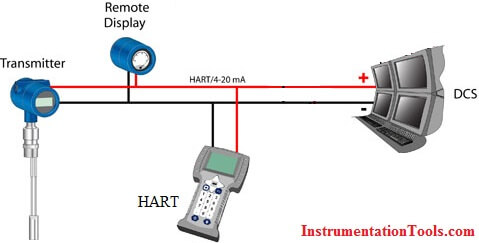
Also, the HART information is easily extracted without interfering with the 4 mA … 20 mA signal used by the host system. Host systems are most commonly a distributed control system (DCS), programmable logic controller (PLC), asset management system, safety system, or a handheld device. HART enables two-way field communication to take place and makes it possible for additional information beyond the normal process variable to be communicated to or from a smart field instrument.
HART – Highway Addressable Remote Transducer Protocol
is an early implementation of Fieldbus, a digital industrial automation protocol. Its most notable advantage is that it can communicate over legacy 4-20 mA analog instrumentation wiring, sharing the pair of wires used by the older system.
Important Points to Consider
- Regardless of the age or capability of your control, safety or asset management system, HART technology can provide additional information to help extend time between shutdowns, lower maintenance cost and improve process performance.
- The two most common tools used to temporarily connect to a HART-enabled device are: a handheld communicator or a PC running a configuration software application and connected via an external modem.
- A handheld communicator or a properly equipped PC can be connected at any point on the loop to access HART Communication data – eliminating the need to be located at or connected to the terminals on the specific device.

- In order to access all of the intelligent information in a specific device, the handheld communicator or the PC-based software application need to contain the current device description (DD) that matches the model and revision level of your device.
- There are 35-40 standard data items in every registered HART device that can be accessed without using the DD.
- Once a device has been configured, the configuration can be saved to facilitate device replacement or maintenance / regulatory record keeping.
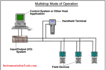
- HART technology can be used on a Point-to-Point basis – monitoring the information from a single device – or on a Multipoint basis – simultaneously monitoring the information from many devices.
- The information from intelligent HART-enabled devices can be monitored for device status alerts on a temporary basis (daily scan of all devices on the network) or can be monitored full-time and the information integrated into the control or monitoring system.
- The translation of the digital HART Protocol signal can be done by an external (or stand alone) device or can be done using a HART-enabled I/O system that allows the termination of the 4-20mA signal to an I/O card. (The Primary Variable is converted to a digital signal and the HART data is translated into digital information, which can be used by the system.)
- The actual conversion or translation of HART Protocol information can be done in the field – close to the HART-enabled device – or in the control or relay room.
- Many products and tools are available to retrofit existing systems to access HART data. With these tools, you can easily replace wire termination boards (in some cases pin-for-pin replacements), which allows the 4-20mA signal to be passed into the control system – unchanged. The HART data is passed to the HART-enabled asset management system.
- Since HART data is read using a modem, it is important to know the ratio of modems to input signals in the HART-enabled I/O. This item is one of the main factors used to determine the scan rate of each signal connected to the I/O card.
- Gateways are used to convert HART Protocol information to other standardized protocols such as HART to Modbus, PROFIBUS, Ethernet, TCP/IP, etc.
- HART multiplexers can be used as the primary I/O front end for a HART-based control or monitoring system
- Not all suppliers implement HART Protocol the same way. It is important to understand how your suppliers implement this enabling technology so that you will be better able to predict performance and results.
- Gaining access and using HART data can be done one loop at a time. Migrating to larger applications will provide full-time monitoring of more devices, therefore increasing the benefit. This scalability offers the User the ability to determine the size and scope of the use of valuable HART Protocol information.
Notes-
- HART technology enables two-way digital communication to occur between intelligent devices and connected host or control systems.
- That HART is an enabling technology meaning that it can be applied in many different application including control, monitoring, safety, asset management, etc.
- HART provides two simultaneous communication channels: the 4-20mA analog signal and a digital signal.
- The digital signal contains information from the device including device status, diagnostics, additional measured or calculated values, etc.
- The 4-20mA signal communicates the primary measured value (in the case of a field instrument) using the 4-20mA current loop.
- The digital communication part of the communication is a request-response communication protocol, which means that during normal operation, each device communication is initiated by a request from a host device.
- The digital signal is made up of two frequencies – 1,200 Hz and 2,200 Hz representing bits 1 and 0. Sine waves of these two frequencies are superimposed on the direct current (dc) analog signal wire to provide simultaneous analog and digital communications.
- A minimum loop impedance of 230 ohms is required for communication.
- HART devices can operate in one of two network configurations-point-to-point or multidrop.
- The HART Command Set includes three classes: universal, common practice, and device specific.
- There are 35-40 data items that are standard in every HART registered device. Host applications may implement any of the necessary commands for a particular application.
- The HART device suppliers provide a DD file for each HART device and the DD file combines all of the information needed by the host application into a single structured file.
- The DD file includes all of the information needed by a host application to fully communicate with the field device and access all of the information available from the device.
- The new HART enhanced Device Description Language extends the capabilities of DDL to provide for advanced visualization of intelligent device information.
- HART Protocol is backward compatible with the installed base of instrumentation and control systems in use today. A new HART-enabled device can replace an existing 4-20mA analog-only device of similar measurement capability without change to the host system or wire.
- Most HART devices provide multiple process variables, which can be used for monitoring or control to gain a better insight into the process.
- Device diagnostics and status information are returned with every communication message.
- The installation practice for a HART communicating device is similar for a conventional 4-20mA instrument.
- HART communicating devices can be used in applications that require IS operation.
Also Read: Intrinsic Safety Protection – ia & ib


awesome sir, you are brilliant
thank you
mANY MANY MANY THANKS