Best practices in PLC wiring (Programmable Logic Controller) are essential for several reasons in industrial automation and control systems.
In the areas of production operations, manufacturing, and energy production, as well as in a wide range of industrial sectors, major components of PLCs help to regulate and monitor different processes.
Best Practices of PLC Wiring
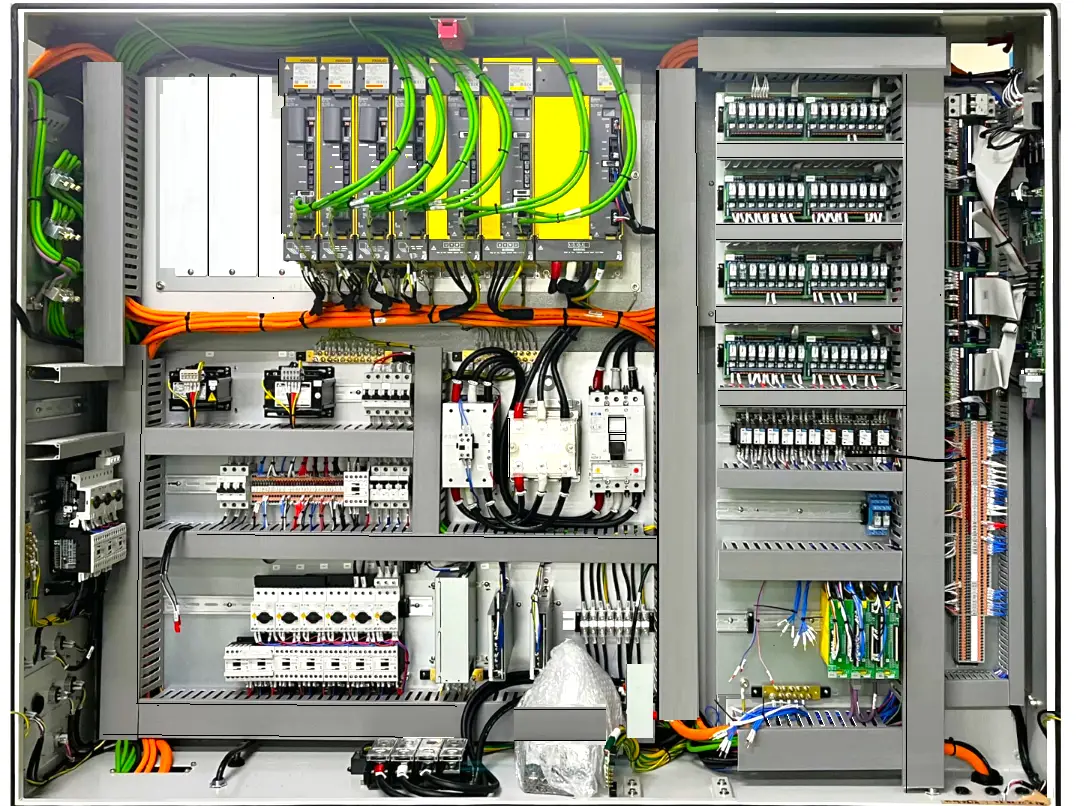
Here are some key reasons why proper PLC wiring is important. In short, it provides Reliability, Safety, Accuracy, Maintenance, Scalability, Compliance, Cost efficiency, and Documentation.
What are the Practices adopted for PLC Wiring?
The wiring of a PLC (Programmable Logic Controller) is a fundamental part of the installation and commissioning of automated control systems. PLCs are used to control various industrial processes and machines.
The wiring connects the PLC to sensors, actuators, and other devices on the factory floor. It ensures the signals are accurately transmitted from the PLC, allowing it to interact with the equipment.
Here are some important practices to adopt when wiring a PLC:
Planning
Before beginning wiring, it is essential to have a clear plan of the layout. It should comprise components, input/output (I/O) devices, and the location of the PLC in the cabinet or electrical panel.
Wiring Drawing
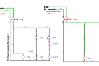
Make sure that, have an updated (revised) copy of the electrical diagram.
Selecting appropriate Cables
Use quality cables that meet the necessary electrical specifications. Make sure they are long enough and have adequate current capacity to avoid signal transmission problems and overheating.
Identification
Clearly label all cables, connectors, and terminals. It simplifies troubleshooting, maintenance, and future expansion. Labeling makes it easy to identify each cable, connector, and terminal within the system.
Labeling helps maintain the integrity of the control system. Mistakenly connecting cables or terminals can lead to equipment damage, system malfunction, or even safety risks. Proper identification reduces the chances of errors during installation or maintenance.
Solid Connections
Ensure secure and safe connections by tightening the terminals to prevent loose connections that may lead to failures.
In industrial plants, downtown can be extremely costly. Loose connections cause unexpected equipment shutdowns or malfunctions, resulting in production delays and financial losses.
Power and Signal Separation
Maintain adequate separation between power cables and signal cables to avoid electromagnetic interference.
Use gutters or dividers to physically separate the cables, if necessary. This can help to prevent cross-talk and reduce the chances of interference.
Testing and Verification
Before energizing the PLC system, performing continuity and verification tests is essential. This is to ensure all components are connected correctly and as per the design specifications. Incorrect connections can lead to malfunctions, inefficiencies, or damage to the equipment.
Safety
Follow electrical safety regulations when wiring. Make sure the PLC and all components are unplugged before working on the wiring.
Documentation
Keep detailed records of all wiring, including up-to-date diagrams, wire lists, and configuration documentation. This will be valuable for future maintenance and future system modifications.
Training
Ensure that personnel who operate and maintain the system are trained in PLC wiring and operation.
Regulatory Compliance
Verify that PLC wiring complies with applicable standards.
Proper wiring is essential to ensure the reliable and safe operation of the system controlled by the PLC.
PLC wiring is crucial for an industrial control system’s reliability, safety, accuracy, and maintainability.
Proper wiring ensures that the control system functions as intended and complies with industry standards and regulations, ultimately contributing to the overall efficiency and success of the industrial process.
Why Proper PLC Wiring is Important?
Proper wiring of a PLC (Programmable Logic Controller) is essential in industrial automation and process control systems for several important reasons:
Proper wiring provides system reliability. Proper wiring ensures a strong and stable cable connection between system components, reducing the likelihood of intermittent failures or communication errors.
It ensures safety. Incorrect wiring can cause short circuits, overloads, and electrical hazards. Proper wiring minimizes the possibility of electrical accidents and ensures that the system meets safety standards.
It improves system performance: Incorrect wiring can negatively impact system performance, causing delays in communication and instruction execution. Proper cabling ensures fast and accurate data transmission.
Proper wiring reduces downtime and maintenance costs. It helps us to carry out simpler maintenance: careful organization and labeling of cables will make it easier to identify and resolve system problems.
Regulatory Compliance: In many industries, some specific regulations and standards require proper wiring to ensure system safety and quality.
PLC Wiring Tips
Here we shared the main points related to the PLC wiring.
- Follow national and local electrical codes.
- Use shielded cables for analog and communication signals.
- Ensure proper grounding of all components.
- Label all wires and terminals.
- Implement a wire color-coding scheme.
- Separate input wiring from output wiring.
- Use the shortest possible cable lengths.
- Avoid looping wires around terminal screws.
- Select appropriate wire gauges for load and current requirements.
- Use wire ferrules for stranded wires.
- Physically separate high-voltage and low-voltage wires.
- Double-check polarity for power supply and I/O connections.
- Bundle wires neatly and use cable ties.
- Test for wire continuity and correct connections before powering up.
- Maintain updated and detailed documentation.
- Utilize terminal blocks for easier maintenance.
- Perform regular wiring inspections.
- Use strain relief mechanisms to protect wires.
- Follow lockout/tagout procedures for safety.
- Conduct thorough system testing after the wiring is complete.
If you liked this article, then please subscribe to our YouTube Channel for Electrical, Electronics, Instrumentation, PLC, and SCADA video tutorials.
You can also follow us on Facebook and Twitter to receive daily updates.
Read Next:
- What is a Dry Contact?
- What is a Wet Contact?
- 4-20 mA Transmitter Wiring
- Why 24 Volts DC Power Supply?
- Interposing Relay Panel Wiring
