Inst ToolsInst ToolsInst Tools
  • Courses
  • Automation
    • PLC
    • Control System
    • Safety System
    • Communication
    • Fire & Gas System
  • Instrumentation
    • Design
    • Pressure
    • Temperature
    • Flow
    • Level
    • Vibration
    • Analyzer
    • Control Valve
    • Switch
    • Calibration
    • Erection & Commissioning
  • Interview
    • Instrumentation
    • Electrical
    • Electronics
    • Practical
  • Q&A
    • Instrumentation
    • Control System
    • Electrical
    • Electronics
    • Analog Electronics
    • Digital Electronics
    • Power Electronics
    • Microprocessor
  • Request
Search
  • Books
  • Software
  • Projects
  • Process
  • Tools
  • Basics
  • Formula
  • Power Plant
  • Root Cause Analysis
  • Electrical Basics
  • Animation
  • Standards
  • 4-20 mA Course
  • Siemens PLC Course
Reading: Structured Text PLC Programming for Automatic Gate Control
Share
Font ResizerAa
Inst ToolsInst Tools
Font ResizerAa
  • Courses
  • Design
  • PLC
  • Interview
  • Control System
Search
  • Courses
  • Automation
    • PLC
    • Control System
    • Safety System
    • Communication
    • Fire & Gas System
  • Instrumentation
    • Design
    • Pressure
    • Temperature
    • Flow
    • Level
    • Vibration
    • Analyzer
    • Control Valve
    • Switch
    • Calibration
    • Erection & Commissioning
  • Interview
    • Instrumentation
    • Electrical
    • Electronics
    • Practical
  • Q&A
    • Instrumentation
    • Control System
    • Electrical
    • Electronics
    • Analog Electronics
    • Digital Electronics
    • Power Electronics
    • Microprocessor
  • Request
Follow US
All rights reserved. Reproduction in whole or in part without written permission is prohibited.
Inst Tools > Blog > PLC Tutorials > Structured Text PLC Programming for Automatic Gate Control

Structured Text PLC Programming for Automatic Gate Control

Design automatic gate control using structured text language with open and close sensors, stop lamp indication, and fault lamp status.

Last updated: September 18, 2024 3:37 pm
Viral Nagda
PLC Tutorials
No Comments
Share
5 Min Read
SHARE

In this post, we will write a logic for controlling the gate of a car passing automatically using structured text language.

Contents
Automatic Gate ControlStructured Text PLC Programming

Automatic Gate Control

Let us understand the case scenario first. There is an automatic gate which is controlled by a motor. The gate is equipped with open and close sensors for sensing the limit. There is a stop lamp indication to avoid collision of cars and a fault lamp indication in case of any malfunction of the system.

There are two gate sensors, one that gives the command to open the gate and one that gives the command to stop the gate. When the open gate command is sensed, the gate opens till the open limit switch is sensed. Then, the system waits for the second car gate sensor to sense.

Once sensed, the gate closes till the close limit switch is sensed. Till the second gate limit is not sensed, a stop lamp will be indicated to avoid any incoming car from coming again (because the existing car has not crossed the gate yet). If any of the limit switches fail to operate in a given time, the fault lamp indicator will turn on.

Also, once the car has entered but not exited within a given time frame, then too the fault lamp will turn on. The operator needs to attend and reset the system to start the system once again. Remember that we have also installed mechanical hard lock limit switches for breaking the electrical supply of the motor in case the limit switch of PLC fails.

Following are the PLC IO’s in this case:

  • Digital inputs – Motor run feedback, open limit switch, close limit switch, gate-1 sensor, gate-2 sensor, and alarm reset push button.
  • Digital outputs – Motor open, motor close, stop lamp, fault lamp.

Structured Text PLC Programming

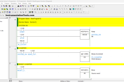
Refer to the below image for the PLC program. In the first part, we will open the gate when the gate-1 sensor is sensed and there is no fault condition present in the system. In this case, the stop lamp too will turn on.

Only the gate open output will turn off when the open limit switch is sensed; the stop lamp will remain on (see we have not unlatched it.)

Structured Text PLC Programming for Automatic Gate Control

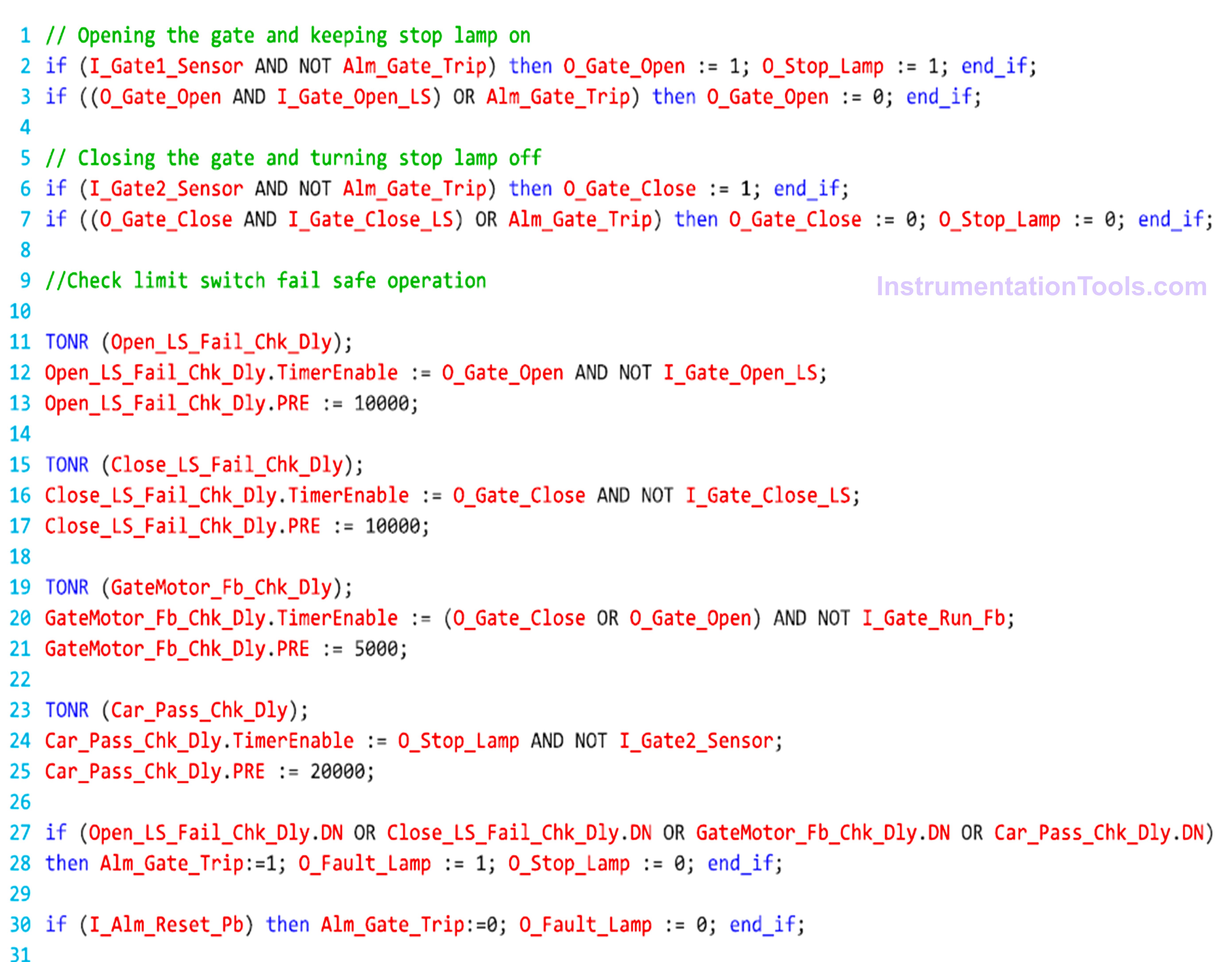
Next, we will close the gate when the gate-2 sensor is sensed and there is no fault condition present in the system. When the gate close limit switch is sensed, then both the outputs of the gate close, and the stop lamp will turn off.

Now, we will create four timers for checking fault conditions. In the first timer, we check if the open limit switch has failed for 10 seconds by seeing whether the open limit switch has not been received even though the gate is open.

In the second timer, we check if the close limit switch has failed for 10 seconds by seeing whether the close limit switch has not been received even though the gate is closed.

In the third timer, we check if the gate motor run feedback has failed for 5 seconds by seeing whether the feedback has not been received even though the gate motor is on.

In the fourth timer, we check if there is any issue in the car passing for 20 seconds by seeing whether the gate-2 sensor has not been received even though the stop lamp is on.

If any of the above timers go on, then a fault will be generated and it will turn off all the outputs and turn on only the fault lamp.

The operator has to press fault reset PB to reset the faults and start the system again.

In this way, we saw how to write a PLC program for automatic gate control using structured text.

Read Next:

  • PLC Program for Sequential Motor Control
  • Sequential PLC Program Pneumatic Valve
  • PLC Program for Water Level Control Logic
  • Structured Text PLC for Sequential Process
  • Write a PLC Program for Selector Machine
Don't Miss Our Updates
Be the first to get exclusive content straight to your email.
We promise not to spam you. You can unsubscribe at any time.
Invalid email address
You've successfully subscribed !

Continue Reading

Download Free HMI software – CODESYS
What is NOR Flash Memory in PLC?
#19 PLC Best Practices – Monitor PLC Memory Usage
Function Block (FB) for Motor Control Logic
What is Human Machine Interface (HMI) ?
Most Asked Questions on SCADA with Answers
Share This Article
Facebook Whatsapp Whatsapp LinkedIn Copy Link
Share
Leave a Comment

Leave a Reply Cancel reply

Your email address will not be published. Required fields are marked *

Stay Connected

128.3kFollowersLike
69.1kFollowersFollow
210kSubscribersSubscribe
38kFollowersFollow

Categories

Explore More

Difference Between PLC and RTU?
Types of Digital Outputs in PLC
Motor ON OFF Logic in PLC
Latched and Momentary Operation of Motor PLC Program
Configuring and Usage of Cyclic Interrupts TIA Portal (OB 30+)
Demo of a SCADA Software – Level Control System
Check Block Consistency Tools in Simatic Manager
Auto Tiffin Box Filling Station

Keep Learning

ControlLogix Architecture - Rockwell Automation

ControlLogix Architecture – Rockwell Automation

PLC Load Memory

What is Resources Tab in the Siemens PLC?

How to Blink Lights in Ladder Logic

How to Blink Lights in Ladder Logic?

What is a Floating License - Automation Software Systems

What is a Floating License? – Automation Software Systems

What is meant by the Batching Process

Batch Simulator PLC Example Program using LogixPro Simulator

Case Statement in SCL Language

Case Statement in SCL Language

Tank Level Control Process in PLC

Tank Level Control in PLC

How to Download Rslogix Free

Download Allen Bradley RSLogix PLC Software

Learn More

Differential Pressure Transmitter with 5 Way Manifold Valve

Differential Pressure Transmitter with 5 Way Manifold Valve

HMI screen for operator

Auto Tiffin Box Filling Station

Kiln

Kiln Inlet Gas Analyzer

Why 4-20 mA Current Signal is used instead of Voltage Signal

Troubleshooting a 4-20mA Current loop

DP transmitter

Square-root characteristics of Differential Pressure Flow Meters

Burning Oven PLC Program

PLC Program for Ceramic Burning Oven Conveyor System

Electrical Machines Questions and Answers

Synchronous Motor Phasor Diagram Questions

how-to-find-resistor-value

Limitations of Resistors

Menu

  • About
  • Privacy Policy
  • Copyright

Quick Links

  • Learn PLC
  • Helping Hand
  • Part Time Job

YouTube Subscribe

Follow US
All rights reserved. Reproduction in whole or in part without written permission is prohibited.
Welcome Back!

Sign in to your account

Username or Email Address
Password

Lost your password?