Inst ToolsInst ToolsInst Tools
  • Ask
  • Courses
  • Videos
  • Q & A
    • Interview
      • Instrumentation
      • Electronics
      • Electrical
      • Practical Questions
    • MCQ
      • Instrumentation MCQ
      • Electrical MCQ
      • Electronics MCQ
      • Control Systems MCQ
      • Analog Electronics MCQ
      • Digital Electronics MCQ
      • Power Electronics MCQ
      • Microprocessor MCQ
      • Multiple Choice Questions
  • EE
    • Electronics
      • Electronics Q & A
      • Electronic Basics
      • Electronic Devices & Circuits
      • Electronics Animation
      • Digital Electronics
    • Electrical
      • Electrical Basics
      • Electrical Q & A
      • Power Electronics
      • Electrical Machines
      • Electrical Animation
      • Power Systems
      • Switchgear & Protection
      • Transmission & Distribution
  • Measure
    • Control Valves
    • Calibration
    • Temperature
    • Pressure
    • Flow
    • Level
    • Analyzers
    • Switches
    • Vibration
    • Solenoid Valve
  • Control
    • PLC Tutorials
    • Control Systems
    • Safety Instrumented System (SIS)
    • Communication
    • Fire & Gas System
  • More
    • Design
    • Tools
    • Animation
    • Basics
    • Formulas
    • Standards
    • TextBooks
    • Common
    • Software
    • Excel Tools
    • Erection & Commissioning
    • Process Fundamentals
    • Videos
    • Books
Search
All rights reserved. Reproduction in whole or in part without written permission is prohibited.
Reading: Air Purge or Air Bubbler Level Measurement
Share
Notification Show More
Font ResizerAa
Inst ToolsInst Tools
Font ResizerAa
  • Courses
  • PLC Tutorials
  • Control Systems
Search
  • Ask
  • Courses
  • Videos
  • Q & A
    • Interview
    • MCQ
  • EE
    • Electronics
    • Electrical
  • Measure
    • Control Valves
    • Calibration
    • Temperature
    • Pressure
    • Flow
    • Level
    • Analyzers
    • Switches
    • Vibration
    • Solenoid Valve
  • Control
    • PLC Tutorials
    • Control Systems
    • Safety Instrumented System (SIS)
    • Communication
    • Fire & Gas System
  • More
    • Design
    • Tools
    • Animation
    • Basics
    • Formulas
    • Standards
    • TextBooks
    • Common
    • Software
    • Excel Tools
    • Erection & Commissioning
    • Process Fundamentals
    • Videos
    • Books
Follow US
All rights reserved. Reproduction in whole or in part without written permission is prohibited.
Inst Tools > Blog > Level Measurement > Air Purge or Air Bubbler Level Measurement

Air Purge or Air Bubbler Level Measurement

Last updated: April 7, 2019 10:44 pm
Editorial Staff
Level Measurement
1 Comment
Share
4 Min Read
SHARE

One of the oldest and simplest methods of level measurement is called the air bubbler, air purge, or dip tube.

With the supply air blocked, as can be seen in the diagram above, the water level in the tube will be equal to that in the tank.

When the air pressure from the regulator is increased until the water in the tube is displaced by air, the air pressure on the tube is equal to the hydrostatic head of the liquid in the tube.

The pressure set in the regulator must overcome the liquid head and bubble up through the measured liquid. This will be indicated by a continuous flow, which is evidence by the formation of bubbles rising to the level of the liquid in the tank.

Air Purge Level Measurement Principle

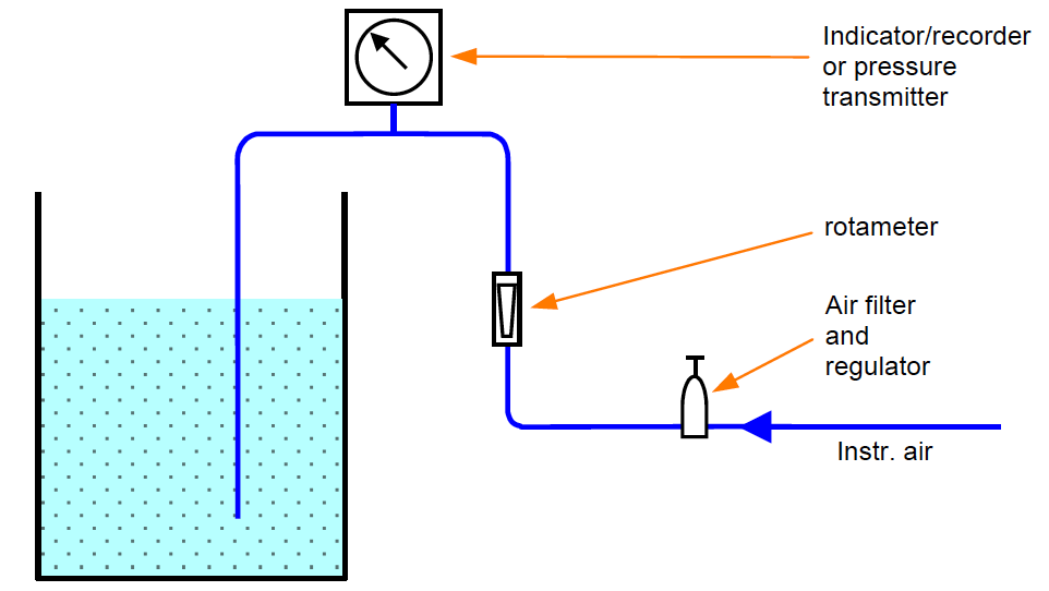
As it may not be convenient to visually inspect the tank for the presence of the bubbles, an air flow indicator will usually be installed in the air line running into the tank.

A rotameter is generally used for this purpose. The importance of maintaining a flow through the tube lies in the fact that the liquid in the tube must be displaced by air and the back pressure on the air line provides the measurement, which is related to level.

The level or static head is measured by an indicator or a DP cells. Readout may be local or remote.

For the closed tank application, the following bubbler system can be used. Two dips are installed with the shorter one dipped for “maximum” level of liquid to be measured, and a longer dip has its tip at “minimum” level.

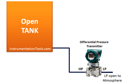
Instrument air is supplied to the system (normally adjusted to 4 bar) at both dips. A DP cell transmitter is placed to sense and measure the level, and produce a proportional 4-20mA signal according to the level.

Closed Tank Air Purge Level Measurement Principle

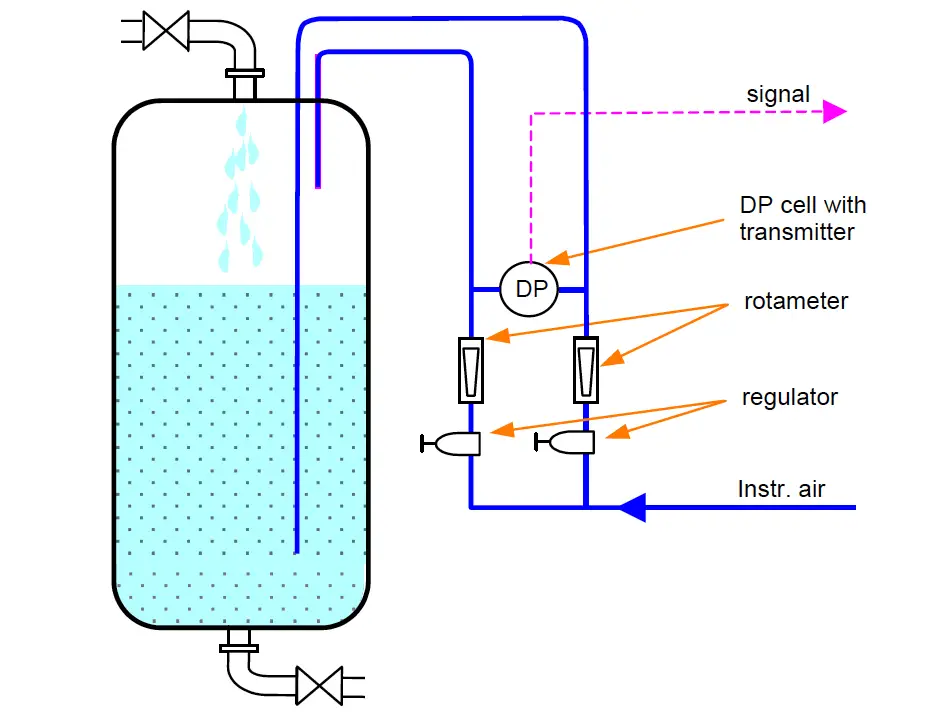
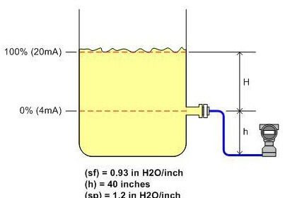
Zero adjustment is initially set-up when the tank or drum is empty, i.e. no differential pressure present.

The “maximum” level is set either by filling the tank/drum with process liquid, or by calculation (if the density of the liquid is known).

An important advantage of the bubbler system is the fact that the measuring instrument can be mounted at any location and elevation with respect to the tank.

This application is advantageous for level measuring applications where it would be inconvenient to mount the measuring instrument at the zero reference level. An example of this situation is level measurement in underground tanks and water wells.

Air and nitrogen are the most commonly used gases for bubbler installations. Liquid may be used if there is reason not to use gas. If process material has a tendency to plug the dip tube, a bypass maybe installed around the flow regulator to blow out the line periodically.

Bubbler systems are used rather infrequently now. One drawback is that it is undesirable in many process to introduce air, nitrogen or other purge material to the process. They do provide economical installation, however, particularly for local readout on clean services.

The accuracy of the bubbler system is about as good as the differential device used for readout. Its accuracy is independent on the constancy of the density of the material whose level is measured.

Source : N. Asyiddin

Don't Miss Our Updates
Be the first to get exclusive content straight to your email.
We promise not to spam you. You can unsubscribe at any time.
Invalid email address
You've successfully subscribed !
Types of Industrial Level Sensors
Remote Seal Transmitters Ranging Calculation
Contact Type Guided Wave Radar Level Transmitter Working Principle
Ultrasonic Level Transmitter Animation
Magnetic Level Indicators Working Animation
Share This Article
Facebook Whatsapp Whatsapp LinkedIn Copy Link
Share
1 Comment
  • Sathiya says:
    April 18, 2017 at 5:00 am

    Any one explain about bubbler open and close tank calculation ?
    And also the pressure setting?

    Reply

Leave a Reply Cancel reply

Your email address will not be published. Required fields are marked *

Stay Connected

128.3kFollowersLike
69.1kFollowersFollow
208kSubscribersSubscribe
38kFollowersFollow

Categories

Recent Comments

  • Guifty Shimica on Top Non-PLC Certification Courses for Automation Professionals
  • Guifty Shimica on Top Non-PLC Certification Courses for Automation Professionals
  • MIHARITSOA Aina Sitraka on Top Non-PLC Certification Courses for Automation Professionals
  • Vaishnavi on Free Instrumentation Course for Trainee Engineers

Related Articles

DP-Level-Transmitter-Diaphragm-with-capillary-tube-type

DP Level Transmitter Calibration for Diaphragm Seal with Capillary

magnetic-level-gauge-principle

Magnetic Level Gauge Working Principle Animation

Nuclear Level Measurement

Nuclear Level Detectors Cascade or Master/Slave concept

Installation and Calibration of Level Transmitter

Installation and Calibration of Level Transmitter

Density Measurement using Remote Seal Transmitters

Remote Seal Differential Pressure Transmitters Principle

Stilling well in liquid level measurement

Stilling Well in Interface Level Measurement System

Contact and Non-Contact Level Sensors

Contact and Non-Contact Level Sensors

Ultrasonic Level Measurement Questions and Answers

Ultrasonic Level Measurement Questions and Answers

More Articles

What is PID Controller

What is PID Controller?

Hydraulic Actuator

Types of Valve Actuators

temperature_calculator

Thermocouple / RTD Calculator

Closed-tank-DP-Level-Transmitter-with-cleaning-leg-Calibration

Closed tank DP Level Transmitter with cleaning leg Calibration

field-transmitter-communication-troubleshooting

Field Transmitter Communication Troubleshooting

FBD Logic

Why different PLC Programming Languages were Developed?

Siemens Profibus Interface DP

How to Create New Project Using Simatic Manager

Process Control Instrumentation Objective Questions

Process Control & Instrumentation Objective Questions – Set 7

Follow US
All rights reserved. Reproduction in whole or in part without written permission is prohibited.
Welcome Back!

Sign in to your account

Username or Email Address
Password

Lost your password?