Inst ToolsInst ToolsInst Tools
  • Courses
  • Automation
    • PLC
    • Control System
    • Safety System
    • Communication
    • Fire & Gas System
  • Instrumentation
    • Design
    • Pressure
    • Temperature
    • Flow
    • Level
    • Vibration
    • Analyzer
    • Control Valve
    • Switch
    • Calibration
    • Erection & Commissioning
  • Interview
    • Instrumentation
    • Electrical
    • Electronics
    • Practical
  • Q&A
    • Instrumentation
    • Control System
    • Electrical
    • Electronics
    • Analog Electronics
    • Digital Electronics
    • Power Electronics
    • Microprocessor
  • Request
Search
  • Books
  • Software
  • Projects
  • Process
  • Tools
  • Basics
  • Formula
  • Power Plant
  • Root Cause Analysis
  • Electrical Basics
  • Animation
  • Standards
  • 4-20 mA Course
  • Siemens PLC Course
Reading: What is a Thermopile ?
Share
Font ResizerAa
Inst ToolsInst Tools
Font ResizerAa
  • Courses
  • Design
  • PLC
  • Interview
  • Control System
Search
  • Courses
  • Automation
    • PLC
    • Control System
    • Safety System
    • Communication
    • Fire & Gas System
  • Instrumentation
    • Design
    • Pressure
    • Temperature
    • Flow
    • Level
    • Vibration
    • Analyzer
    • Control Valve
    • Switch
    • Calibration
    • Erection & Commissioning
  • Interview
    • Instrumentation
    • Electrical
    • Electronics
    • Practical
  • Q&A
    • Instrumentation
    • Control System
    • Electrical
    • Electronics
    • Analog Electronics
    • Digital Electronics
    • Power Electronics
    • Microprocessor
  • Request
Follow US
All rights reserved. Reproduction in whole or in part without written permission is prohibited.
Inst Tools > Blog > Temperature Measurement > What is a Thermopile ?

What is a Thermopile ?

Last updated: July 19, 2018 2:56 pm
Editorial Staff
Temperature Measurement
No Comments
Share
5 Min Read
SHARE

A thermopile is an electronic device that converts thermal energy into electrical energy. It is composed of several thermocouples connected usually in series or, less commonly, in parallel.

Thermocouples operate by measuring the temperature differential from their junction point to the point in which the thermocouple output voltage is measured. Thermocouples can be connected in series as thermocouple pairs with a junction located on either side of a thermal resistance layer. The output from the thermocouple pair will be a voltage that is directly proportional to the temperature difference across the thermal resistance layer and also to the heat flux through the thermal resistance layer. Adding more thermocouple pairs in series increases the magnitude of the voltage output. Thermopiles can be constructed with a single thermocouple pair, composed of two thermocouple junctions, or multiple thermocouple pairs.

A thermopile is a serially-interconnected array of thermocouples, each of which consists of two dissimilar materials with a large thermo-electric power and opposite polarities. The thermocouples are placed across the hot and cold regions of a structure and the hot junctions are thermally isolated from the cold junctions. The cold junctions are typically placed on the silicon substrate to provide effective heat sink. In the hot regions, there is a black body for absorbing the infrared, which raises the temperature according to the intensity of the incident infrared. These thermopiles employ two different thermoelectric materials which are placed on a thin diaphragm having a low thermal conductance and capacitance.

Thermopile Working Principle

A thermopile is an array of several thermocouples connected in series. A thermopile with N thermocouples will output a voltage N times bigger than the one produced by a single thermocouple, increasing the sensitivity of the transducer. With enough elements in the thermopile, a useful voltage can be generated in order to control another process. This type of transducer is often used to measure heat flux.

Thermopiles do not respond to absolute temperature, but generate an output voltage proportional to a temperature difference or temperature gradient.

Thermopiles are used to provide an output in response to temperature as part of a temperature measuring device, such as the infrared thermometers widely used by medical professionals to measure body temperature , or in thermal accelerometers to measure the temperature profile inside the sealed cavity of the sensor. . They are also used widely in heat flux sensors and gas burner safety controls.

The output of a thermopile is usually in the range of tens or hundreds of millivolts. As well as increasing the signal level, the device may be used to provide spatial temperature averaging.

Thermopiles are also used to generate electrical energy from, for instance, heat from electrical components, solar wind, radioactive materials, or combustion. The process is also an example of the Peltier Effect (electric current transferring heat energy) as the process transfers heat from the hot to the cold junctions.

Applications:

Thermopile detectors are thermal detectors that utilize the Seebeck effect in which a thermal electromotive force is generated in proportion to the incident infrared light energy. Thermopile detectors themselves have no wavelength dependence and so are used with various types of window materials for diverse applications such as temperature measurement, human body sensing, and gas analysis.

Advantages of Thermopile 

  • No need of external power supply
  • Stable response to DC radiation omitted from temperature measuring bodies
  • Stable Response Characteristics

Differential Temperature Thermopile

Thermopile Principle

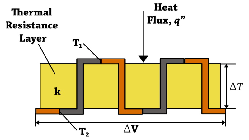
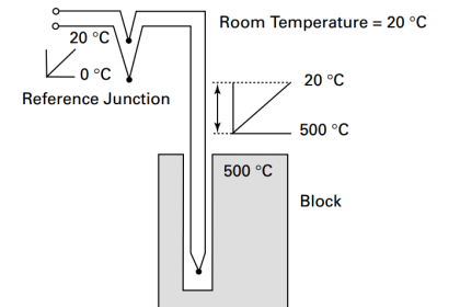
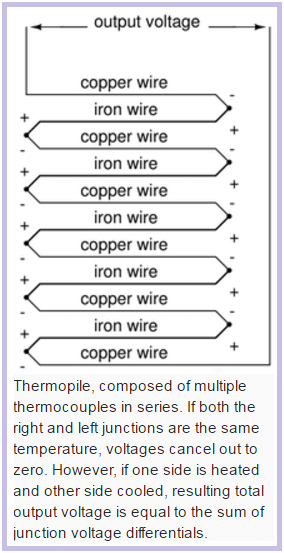
Diagram of a differential temperature thermopile with two sets of thermocouple pairs connected in series shown above. The two top thermocouple junctions are at temperature T1 while the two bottom thermocouple junctions are at temperature T2. The output voltage from the thermopile, ΔV, is directly proportional to the temperature differential, ΔT or T1 – T2, across the thermal resistance layer and number of thermocouple junction pairs. The thermopile voltage output is also directly proportional to the heat flux, q”, through the thermal resistance layer.

Also Read: How a 4 Wire RTD Works ?

Don't Miss Our Updates
Be the first to get exclusive content straight to your email.
We promise not to spam you. You can unsubscribe at any time.
Invalid email address
You've successfully subscribed !

Continue Reading

Thermocouple Properties, Temperature Ranges, Element Construction
Resistance Temperature Detectors Working Principle
Helix Bimetallic Thermometer Principle
Why Thermocouple Reference Junction Compensation Required ?
Temperature Sensor Failure
What is RTD Sensitivity ?
Share This Article
Facebook Whatsapp Whatsapp LinkedIn Copy Link
Share
Leave a Comment

Leave a Reply Cancel reply

Your email address will not be published. Required fields are marked *

Stay Connected

128.3kFollowersLike
69.1kFollowersFollow
210kSubscribersSubscribe
38kFollowersFollow

Categories

Explore More

How to Install Thermowell on an Elbow?
Temperature Coefficient of Resistance (α)
How to Convert 2 wire RTD into 3 or 4 wire RTD?
Response Time Test of RTD and Thermocouple
Pneumatic Temperature Transmitter with Sensor Principle
Thermocouples Burnout detection
Manually Interpreting Thermocouple Voltages
Liquid In Glass Thermometer Principle

Keep Learning

Thermowell Installation near Critical Equipment

Thermowell Installation near Critical Equipment

Electrical Resistance Temperature Curves of RTD

Resistance Temperature Detectors (RTD) Construction

Thermovcouple Circuit

Thermocouple and its Principle

What is an RTD

Components of RTD

Four Wire RTD Circuit

What is a Four-wire RTD ?

Temperature Transmitter with Thermocouple

Thermocouple Extension and Compensating Cables

How to Test a Thermocouple with a Multimeter

Testing a Thermocouple With a Multimeter

RTD installed after the Orifice Plate

Why RTD installed after the Orifice Plate ?

Learn More

HMI screen for operator

#8 PLC Best Practices – Validate HMI Input Variables at PLC Level

Open User Communication in Siemens Tia Portal - PLC to PLC

Open User Communication in Siemens Tia Portal – PLC to PLC

Magnetic Level Gauge Float

Magnetic Level Gauge Float Design

Magnehelic Gauge Calibration

Magnehelic Gauge Calibration

Strain Gauge Pressure Sensor Principle

Strain Gauge Pressure Sensor Principle

Automated Test Bench - Complex PLC Programming Examples

Automated Test Bench – Complex PLC Programming Examples

Single-beam non-dispersive analyzer

Single-beam Non-dispersive Analyzer

PLC Program for Control Valve Scaling

PLC Program for Control Valve Scaling

Menu

  • About
  • Privacy Policy
  • Copyright

Quick Links

  • Learn PLC
  • Helping Hand
  • Part Time Job

YouTube Subscribe

Follow US
All rights reserved. Reproduction in whole or in part without written permission is prohibited.
Welcome Back!

Sign in to your account

Username or Email Address
Password

Lost your password?