Inst ToolsInst ToolsInst Tools
  • Courses
  • Automation
    • PLC
    • Control System
    • Safety System
    • Communication
    • Fire & Gas System
  • Instrumentation
    • Design
    • Pressure
    • Temperature
    • Flow
    • Level
    • Vibration
    • Analyzer
    • Control Valve
    • Switch
    • Calibration
    • Erection & Commissioning
  • Interview
    • Instrumentation
    • Electrical
    • Electronics
    • Practical
  • Q&A
    • Instrumentation
    • Control System
    • Electrical
    • Electronics
    • Analog Electronics
    • Digital Electronics
    • Power Electronics
    • Microprocessor
  • Request
Search
  • Books
  • Software
  • Projects
  • Process
  • Tools
  • Basics
  • Formula
  • Power Plant
  • Root Cause Analysis
  • Electrical Basics
  • Animation
  • Standards
  • 4-20 mA Course
  • Siemens PLC Course
Reading: Air Pressure Regulator Questions
Share
Notification Show More
Font ResizerAa
Inst ToolsInst Tools
Font ResizerAa
  • Courses
  • Design
  • PLC
  • Interview
  • Control System
Search
  • Courses
  • Automation
    • PLC
    • Control System
    • Safety System
    • Communication
    • Fire & Gas System
  • Instrumentation
    • Design
    • Pressure
    • Temperature
    • Flow
    • Level
    • Vibration
    • Analyzer
    • Control Valve
    • Switch
    • Calibration
    • Erection & Commissioning
  • Interview
    • Instrumentation
    • Electrical
    • Electronics
    • Practical
  • Q&A
    • Instrumentation
    • Control System
    • Electrical
    • Electronics
    • Analog Electronics
    • Digital Electronics
    • Power Electronics
    • Microprocessor
  • Request
Follow US
All rights reserved. Reproduction in whole or in part without written permission is prohibited.
Inst Tools > Blog > Control Valves > Air Pressure Regulator Questions

Air Pressure Regulator Questions

Air Pressure Regulator regulates the fluctuating air pressure from the receiver vessel down to a lower, more constant level.

Last updated: September 9, 2020 12:16 pm
Editorial Staff
Control Valves Practical Questions
No Comments
Share
4 Min Read
SHARE

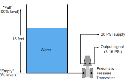
Since precision pneumatic instruments operate best when their supply air pressure is at a constant pressure, it is necessary to regulate the fluctuating air pressure from the receiver vessel down to a lower, more constant level for the instrument. The device designed to do this is called an air pressure regulator.

Air Pressure Regulator

A cut-away diagram of an air pressure regulator is shown here:

Air Pressure Regulator cut-away diagram

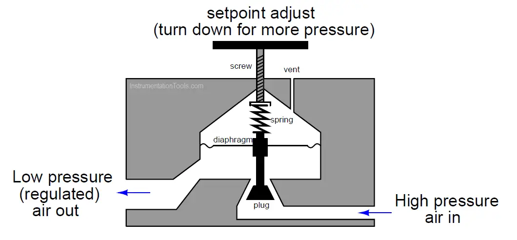
The wedge-shaped plug can move down to open the passageway and allow more of the high-pressure air to enter the chamber below the diaphragm, and can move up to close off the passageway and reduce the flow of incoming air into the diaphragm chamber. The regulation setpoint is adjustable by the position of the threaded rod pressing down on the diaphragm through a spring.

Describe how this air pressure regulator functions. Suppose that the outlet air pressure is below setpoint. How does this mechanism respond to bring the outlet pressure back up to where it is supposed to be?

If the outlet air pressure rises to too high a level, how does the mechanism compensate to reduce it back down to the setpoint level?

Answer:

If the chamber air pressure is too high, the excess pressure will exert more force on the underside of the diaphragm to push it up, thus moving the plug up and closing off the passageway, reducing the air supply flow:

Pressure Regulator

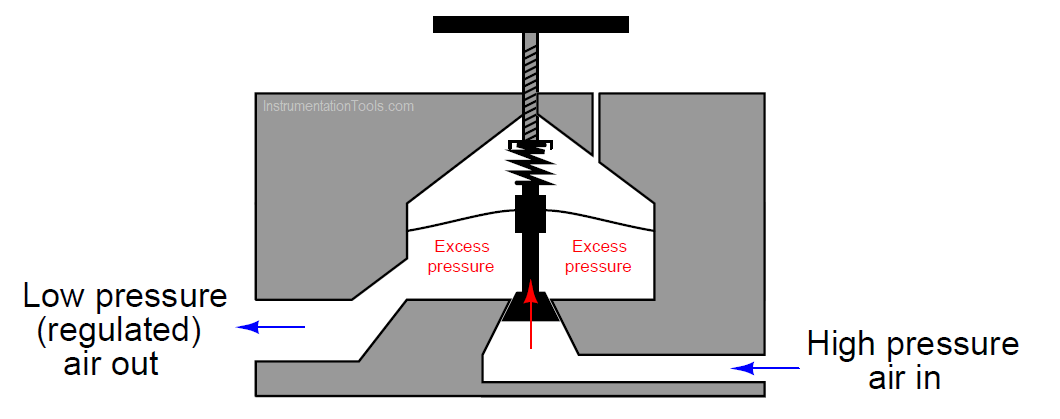
As the outlet air continues to flow out of the regulator, the chamber pressure will eventually drop back down to setpoint, and the passageway will open again.

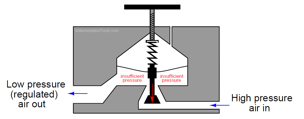
If the chamber air pressure is too low, the reduced force on the underside of the diaphragm cannot resist the spring force from above, and the plug moves down. This opens up the passageway, allowing more of the supply air to enter the chamber and increase the pressure:

Pneumatic Pressure Regulator

In short, the opposing forces of spring pressure (and atmospheric air pressure) above the diaphragm, versus the chamber pressure below the diaphragm, act to move the plug up or down as needed to maintain the chamber pressure approximately equal to the equivalent pressure of atmospheric air + spring force on the diaphragm.

The threaded rod with an attached turn handle adjusts the compression of the spring above the diaphragm, and changes the pressure regulation setpoint. Screwing the threaded rod in the downward direction will increase the spring force on the top of the diaphragm and likewise increase the equilibrium point between the three forces, increasing the output air pressure regulation setpoint as a consequence.

Screwing the threaded rod in the upward direction will decrease the spring force on the diaphragm’s top, decreasing the equilibrium point between the three forces and decreasing the pressure setpoint.

Questions for you:

1. Suppose the spring inside this regulator were to break. What effect would this have on the regulator’s output pressure, and why?

2. Suppose the vent hole were to plug. What effect would this have on the regulator’s output pressure, and why?

Share your answers with us through below comments section.

Read Next:

  • Heat Exchanger DP Transmitter
  • P&ID Guidelines for Valves
  • Single Block and Bleed Valve
  • Why Use a Current Loop?
  • Basics of Voltage Regulator

Credits: Tony R. Kuphaldt

Don't Miss Our Updates
Be the first to get exclusive content straight to your email.
We promise not to spam you. You can unsubscribe at any time.
Invalid email address
You've successfully subscribed !

Continue Reading

Troubleshoot Allen Bradley PLC Logic
Control Valve Passing Problem after Overhauling Job
Types of Pilot Operated Diaphragm Solenoid Valve Principle
What is Control Valve Flashing ?
A Question on Steam Drum Water Level Measurement
Smart DP Transmitter Flow Meter Calculations
Share This Article
Facebook Whatsapp Whatsapp LinkedIn Copy Link
Share
Leave a Comment

Leave a Reply Cancel reply

Your email address will not be published. Required fields are marked *

Stay Connected

128.3kFollowersLike
69.1kFollowersFollow
210kSubscribersSubscribe
38kFollowersFollow

Categories

Explore More

Inherent vs Installed Control Valve Flow Characteristics
Control Valve Tips and Tricks
DP Transmitter Located 10 feet Beneath the Vessel
Solenoid Valves Types & Functions
Pilot-operated Relief Valve Principle
Butterfly Valves Construction, Types, Stem & Bonnet Assembly
How to Install a Control Valve?
Calculate 0%, 50%, and 100% Calibration Points for ΔP transmitter

Keep Learning

Y Body Globe Valve

Globe Valve Body Design

Reduce Control Valve Noise

How to Reduce the Control Valve Noise?

Valves MCQ

Valves MCQ

Rotary Stem Valves

Rotary Stem Valves

electric motor actuator principle

What is a Electric Motor Actuator ?

DP transmitter Errors

DP Transmitter Calibration Errors

Hydraulic Actuators

Working Principle of Hydraulic Actuators

Common Valve Abbreviations

Common Valve Abbreviations in US Engineering Drawings

Learn More

Difference between Calibration and Ranging

Difference between Calibration and Ranging

Chemical Dosing Control System

Introduction to Chemical Dosing System

DeltaV Tune Tutorial

How to Tune a Loop in DeltaV System

Creating CNC Program

Steps Followed Before Creating CNC Program

Relay-Operation

Relay Working Animation

Process vessel for measuring water level

Level Measurement Lab Exercise

Force Balance Pressure Transmitters

Pneumatic Pressure Transmitters Principle

IP Ratings and Equivalent NEMA Ratings

IP Ratings and Equivalent NEMA Ratings

Menu

  • About
  • Privacy Policy
  • Copyright

Quick Links

  • Learn PLC
  • Helping Hand
  • Part Time Job

YouTube Subscribe

Follow US
All rights reserved. Reproduction in whole or in part without written permission is prohibited.
Welcome Back!

Sign in to your account

Username or Email Address
Password

Lost your password?