Inst ToolsInst ToolsInst Tools
  • Courses
  • Automation
    • PLC
    • Control System
    • Safety System
    • Communication
    • Fire & Gas System
  • Instrumentation
    • Design
    • Pressure
    • Temperature
    • Flow
    • Level
    • Vibration
    • Analyzer
    • Control Valve
    • Switch
    • Calibration
    • Erection & Commissioning
  • Interview
    • Instrumentation
    • Electrical
    • Electronics
    • Practical
  • Q&A
    • Instrumentation
    • Control System
    • Electrical
    • Electronics
    • Analog Electronics
    • Digital Electronics
    • Power Electronics
    • Microprocessor
  • Request
Search
  • Books
  • Software
  • Projects
  • Process
  • Tools
  • Basics
  • Formula
  • Power Plant
  • Root Cause Analysis
  • Electrical Basics
  • Animation
  • Standards
  • 4-20 mA Course
  • Siemens PLC Course
Reading: Basics of Voltage Regulator
Share
Font ResizerAa
Inst ToolsInst Tools
Font ResizerAa
  • Courses
  • Design
  • PLC
  • Interview
  • Control System
Search
  • Courses
  • Automation
    • PLC
    • Control System
    • Safety System
    • Communication
    • Fire & Gas System
  • Instrumentation
    • Design
    • Pressure
    • Temperature
    • Flow
    • Level
    • Vibration
    • Analyzer
    • Control Valve
    • Switch
    • Calibration
    • Erection & Commissioning
  • Interview
    • Instrumentation
    • Electrical
    • Electronics
    • Practical
  • Q&A
    • Instrumentation
    • Control System
    • Electrical
    • Electronics
    • Analog Electronics
    • Digital Electronics
    • Power Electronics
    • Microprocessor
  • Request
Follow US
All rights reserved. Reproduction in whole or in part without written permission is prohibited.
Inst Tools > Blog > Electronic Basics > Basics of Voltage Regulator

Basics of Voltage Regulator

Last updated: August 4, 2017 4:04 am
Editorial Staff
Electronic Basics
No Comments
Share
4 Min Read
SHARE

Voltage Regulator

The 78XX series of linear voltage regulators provide positive fixed output voltages for a range of values. The last two digits in the part number indicate the output voltage value and the first two digits indicate Polarity of the voltage ( 78 for Positive and 79 for Negative ). The 7812 provides a +12 V regulated output. The change in output voltage for a specified change in input voltage is called the line regulation. The change in output voltage for a specified change in load current is called the load regulation. These parameters are specified on the datasheet.

It is recommended by the manufacturer that a 0.33 mF capacitor be connected from the input terminal to ground and a 0.1 mF connected from the output terminal to ground, as shown in Below Figure to prevent high-frequency oscillations and improve the performance. You may wonder about putting a small-value capacitor in parallel with a large one; the reason is that the large filter capacitor has an internal equivalent series resistance, which affects the high frequency response of the system. The effect is cancelled with the small capacitor.

Voltage Regulator Circuit

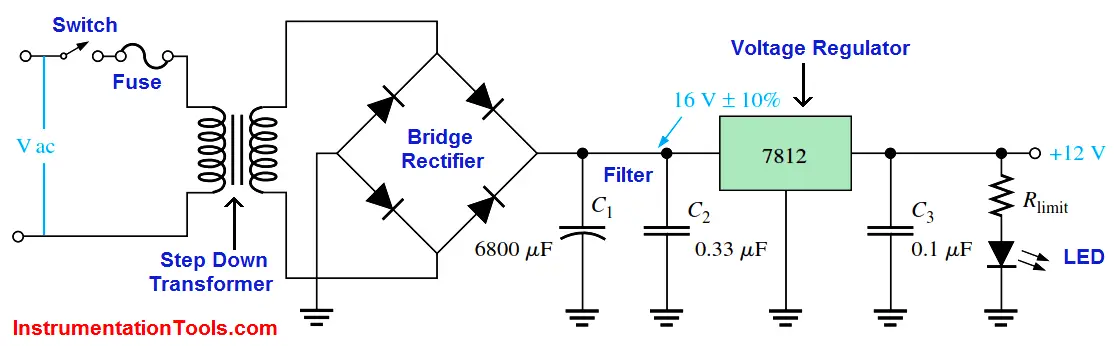
Fig : 12V Regulated Power Supply Circuit

Voltage Points in the Circuit:

  1. Step Down Transformer : Transformer steps down from 230V AC to 24V AC
  2. Full wave Bridge Rectifier : converts 24V AC into Pulsating 24V DC ( includes AC ripples)
  3. Capacitor Filter : Removes the AC ripples
  4. Voltage Regulator : Provides fixed +12V DC output to the load.

IC Voltage Regulator

A Voltage Regulator (also called a “regulator”) has only three legs and appears to be a comparatively simple device but it is actually a very complex integrated circuit. A regulator converts varying input voltage and produces a constant “regulated” output voltage. Voltage regulators are available in a variety of outputs, typically 5 volts, 9 volts and 12 volts. The first two digits indicates Polarity and the last two digits in the name indicate the output voltage.

Fixed Positive Voltage Regulator

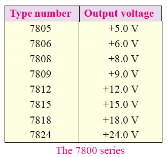
This IC regulator provides a fixed positive output voltage. Although many types of IC regulators are available, the 7800 series of IC regulators is the most popular. The last two digits in the part number indicate the d.c. output voltage. For example [See Table below], the 7812 is a + 12V regulator whereas the 7805 is a + 5V regulator. Note that this series (7800 series) provides fixed regulated voltages from + 5 V to + 24V.

7805 Voltage Regulator

Fixed Negative Voltage Regulator

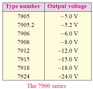
This IC regulator provides a fixed negative ouput voltage. The 7900 series of IC regulators is commonly used for this purpose. This series (7900) is the negative-voltage counterpart of the7800 series [See Table below]. Note that 7900 series provides fixed regulated voltages from – 5V to – 24 V.

7900 Fixed Negative Voltage Regulator

Note : We replace the Voltage Regulator IC with required output voltage & polarity in the above circuit.

Don't Miss Our Updates
Be the first to get exclusive content straight to your email.
We promise not to spam you. You can unsubscribe at any time.
Invalid email address
You've successfully subscribed !

Continue Reading

How to Test a Diode using Multimeter
What is Contactor ?
Difference between Intrinsic and Extrinsic Semiconductors
Types of Potentiometers – What is a Potentiometer? – Applications
Top Beginner Soldering Mistakes and How to Avoid Them?
How to Measure Duty Cycle using Multimeter
Share This Article
Facebook Whatsapp Whatsapp LinkedIn Copy Link
Share
Leave a Comment

Leave a Reply Cancel reply

Your email address will not be published. Required fields are marked *

Stay Connected

128.3kFollowersLike
69.1kFollowersFollow
210kSubscribersSubscribe
38kFollowersFollow

Categories

Explore More

What is a Fuse ?
Difference Between LDR and Photodiode
How are Silicon Chips Disposed?
How does SMPS Works? – Switched Mode Power Supply
How to Test a Transistor using Multimeter
IEC labelling for Resistors Color Code
Difference Between Electrical and Electronic Devices
Things to Know When Measuring Current

Keep Learning

Accuracy, resolution, range, counts, digits and precision

Definition of Accuracy, Precision, Resolution, Range

Zener Diode Regulator

Zener Diode Voltage Regulators

How to Test a Battery using Multimeter

How to Test a Battery using a Multimeter?

What is PCB Corrosion - Electronic Boards Corrosion Prevention

What is PCB Corrosion? Electronic Boards Corrosion Prevention

Difference Between Clamp Meters and Digital Multimeters

Difference Between Clamp Meters and Multimeters

What is a Non-Linear Device

What is a Non-Linear Device? Example – Advantages

Difference Between LED and LCD

Difference Between LED and LCD

Continuity Testing using Multimeter

How to do Continuity Testing using Multimeter

Learn More

Omron PLC Instructions - Move, Move Bit, Move Digit

Move, Move Bit, Move Digit – Examples of Omron PLC Programs

Process Control System

Basics of Process Control Systems

Valve Software

Free Control Valve Software Download

LC Tuned circuit Working Animation

LC Tuned circuit Working Animation

Temperature Switch Working

Basics of Temperature Switch

Logic Solver in Safety PLC

What is a Logic Solver? – Safety PLC

Automatic Lamp Control in Storage Facility

PLC Program for Automatic Lamp Control in Storage Facility

Oval gear Flow Meter Principle

Oval Gear Meter – Principle, Advantages, Limitations, Applications

Menu

  • About
  • Privacy Policy
  • Copyright

Quick Links

  • Learn PLC
  • Helping Hand
  • Part Time Job

YouTube Subscribe

Follow US
All rights reserved. Reproduction in whole or in part without written permission is prohibited.
Welcome Back!

Sign in to your account

Username or Email Address
Password

Lost your password?