Each student must set the level measurement range of their team’s transmitter, the LRV and URV point determined by the instructor (pieces of tape or zip-ties placed on the process vessel sight-glass).
Transmitters must be ranged without the benefit of filling and draining the actual process vessel as part of the procedure, because in industry we usually do not have the luxury of altering the liquid’s actual level as part of our instrument commissioning. Each student will have the LRV and URV points individually set by the instructor.
Transmitter Ranging
Prior to ranging the transmitter, it should be calibrated against a trusted standard. For non-contact echo-based instruments, this may be done using the floor as a reference, raising the instrument above floor level and checking its height using a tape measure or ruler.
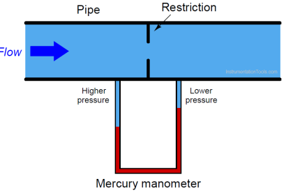
For pressure-based instruments sensing liquid level by the principle of hydrostatic pressure, a manometer may be most appropriate.
In either case, you are expected to demonstrate the proper use of a manometer to measure low air pressures, so if this happens to work well as a calibration standard for your team’s transmitter it makes sense to perform the calibration while demonstrating the use of the manometer.
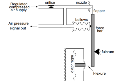
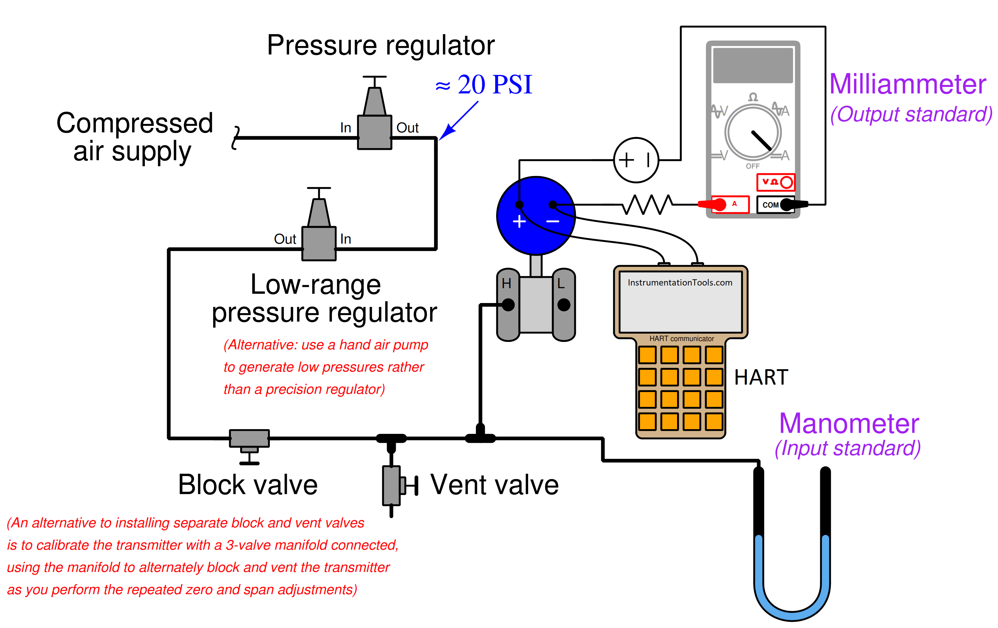
One method for generating the low air pressures required for this calibration is to use a special low-range pressure regulator as shown here:
Typical calibration setup for a low-range electronic pressure transmitter
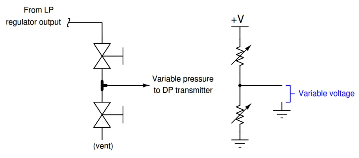
If the low-range pressure regulator does not reliably generate low enough pressures, you may throttle both the block and vent valves, using them as a sort of “pressure divider” (analogous to two resistors throttling current to make a voltage divider) to apply a lower pressure to the manometer and DP transmitter than the regulator outputs:
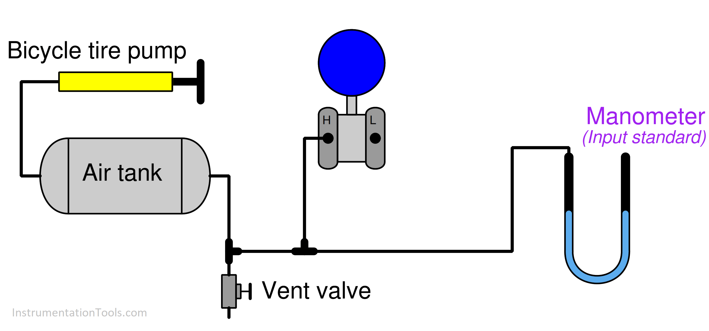
An alternative method for generating very low air pressures is to use a small-volume air pump (e.g. a bicycle tire pump works well for this purpose) connected to a chamber of large volume, such that each stroke of the pump results in a tiny increment of pressure increase applied to the manometer and DP transmitter:
An alternative source of low-pressure air for calibration
As with all modern smart transmitters, you need only calibrate the transmitter against trusted pressure and current standards once, and after that, you may re-range the LRV and URV points as many times as you wish by typing values into the HART communicator.
It is recommended that you work as a team to calibrate your transmitter at the same time you complete the “Manometer usage” objective. After that, each student on the team completes their “Loop ranging” objective individually.
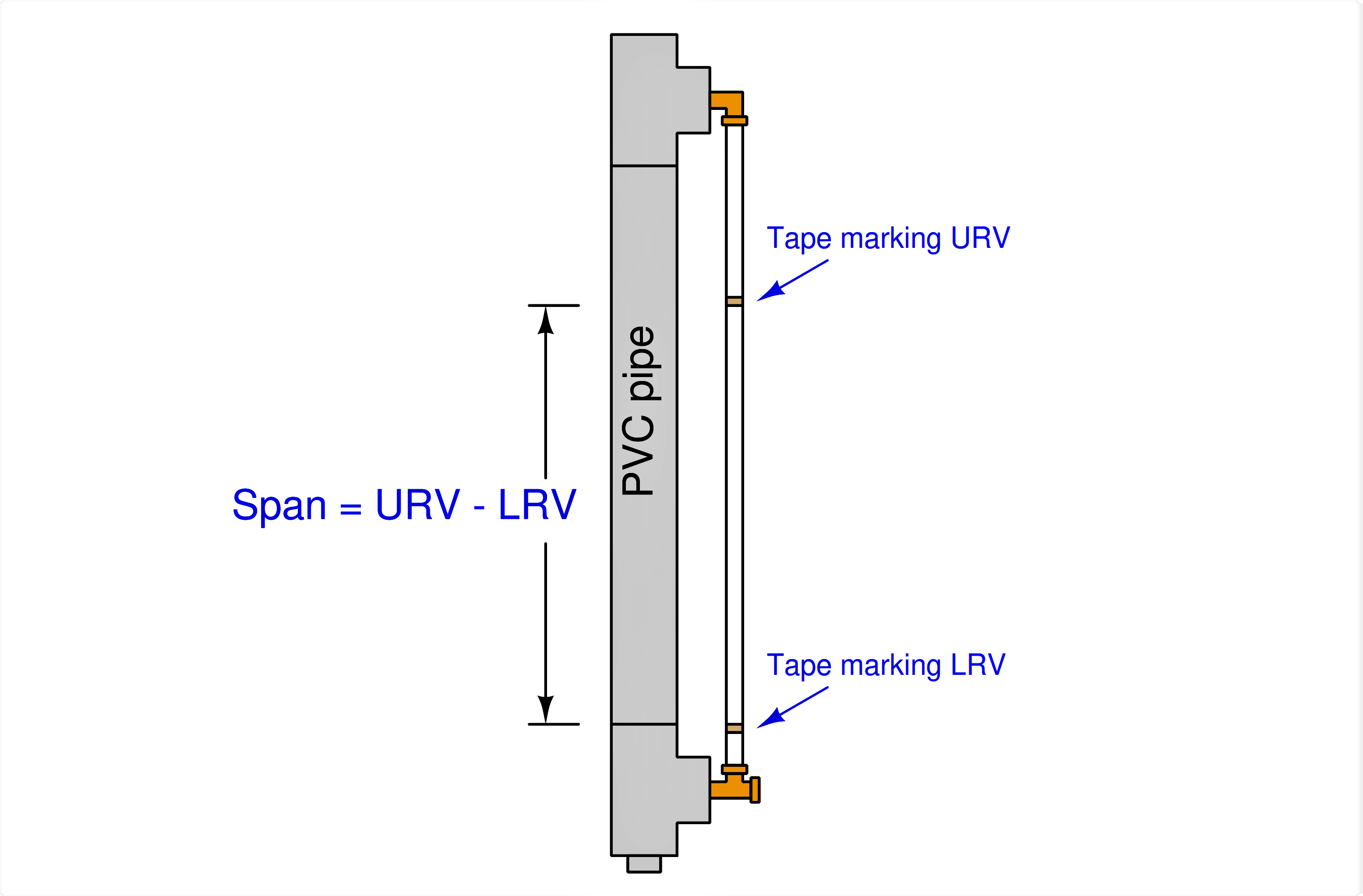
The span of your instrument’s range will be dictated by the distance between the LRV and URV points chosen by your instructor, and the zero of your instrument’s range (its LRV) will be dictated by the location of the LRV point and the transmitter’s mounting height (i.e. the amount of suppression).
Your electronic indicator (or recorder, or indicating controller) must display the process vessel’s level in units of inches, with the indication showing “0” when the vessel’s liquid level is at the LRV point.
You must use whatever liquid level happens to be in the vessel at the time of transmitter installation as a reference for setting the zero because this represents the kind of realism you will face on the job: operators are unlikely to let you interrupt production by significantly altering the amount of level in their process vessel just to range a level transmitter.
If the transmitter is correctly calibrated (against a trusted standard) and field-ranged to match the liquid level, it should reliably indicate the liquid level at any point within the set range.
It would be easy to set the LRV and URV points of your smart transmitter if you had the freedom to drain and fill the vessel at will:
simply drain the vessel to the LRV point, then set the transmitter’s LRV to the live pressure value indicated on the HART communicator’s display;
next, fill the vessel to the URV point, then set the transmitter’s URV to the pressure value indicated. However, since you will not be allowed to do this, you must devise your own procedure for accurately setting the smart transmitter’s LRV and URV while the liquid level is at some point not of your choosing. (Hint: you will need to use a tape measure!) The instructor will ask you to explain your procedure, and why it works.
The accuracy of your calibration will be checked by the instructor, filling and emptying your process vessel while checking the indicator to make sure it reads 0 inches at the LRV level and full height at the URV level.
Again, you are not allowed to fill and empty the vessel as part of your ranging procedure, but only the instructor is allowed to do this as a final check of your work!
Common Mistakes
Applying excessive air pressure to a manometer, and blowing all the liquid out of it (when using a regulator as the calibration air pressure source)!
Improper pipe/tube fitting installation (e.g. trying to thread tube fittings into pipe fittings and viceversa).
Mounting the transmitter above the LRV point, rather than below (to avoid loss of impulse line liquid fill when the vessel’s level is drained to the LRV point).
Neglecting to drain all liquid out of the transmitter prior to applying air pressure at the calibration bench (this will likely blow liquid into the tubes, causing calibration errors).
Neglecting to bleed all air out of the impulse line and transmitter body when installing the transmitter at the liquid process vessel (this will cause zero- and span-shift errors).
Read Next:
Credits: Tony R. Kuphaldt