Inst ToolsInst ToolsInst Tools
  • Courses
  • Automation
    • PLC
    • Control System
    • Safety System
    • Communication
    • Fire & Gas System
  • Instrumentation
    • Design
    • Pressure
    • Temperature
    • Flow
    • Level
    • Vibration
    • Analyzer
    • Control Valve
    • Switch
    • Calibration
    • Erection & Commissioning
  • Interview
    • Instrumentation
    • Electrical
    • Electronics
    • Practical
  • Q&A
    • Instrumentation
    • Control System
    • Electrical
    • Electronics
    • Analog Electronics
    • Digital Electronics
    • Power Electronics
    • Microprocessor
  • Request
Search
  • Books
  • Software
  • Projects
  • Process
  • Tools
  • Basics
  • Formula
  • Power Plant
  • Root Cause Analysis
  • Electrical Basics
  • Animation
  • Standards
  • 4-20 mA Course
  • Siemens PLC Course
Reading: AC Induction Motor Slip
Share
Font ResizerAa
Inst ToolsInst Tools
Font ResizerAa
  • Courses
  • Design
  • PLC
  • Interview
  • Control System
Search
  • Courses
  • Automation
    • PLC
    • Control System
    • Safety System
    • Communication
    • Fire & Gas System
  • Instrumentation
    • Design
    • Pressure
    • Temperature
    • Flow
    • Level
    • Vibration
    • Analyzer
    • Control Valve
    • Switch
    • Calibration
    • Erection & Commissioning
  • Interview
    • Instrumentation
    • Electrical
    • Electronics
    • Practical
  • Q&A
    • Instrumentation
    • Control System
    • Electrical
    • Electronics
    • Analog Electronics
    • Digital Electronics
    • Power Electronics
    • Microprocessor
  • Request
Follow US
All rights reserved. Reproduction in whole or in part without written permission is prohibited.
Inst Tools > Blog > Electrical Theory > AC Induction Motor Slip

AC Induction Motor Slip

Last updated: August 6, 2018 1:41 pm
Editorial Staff
Electrical Theory
No Comments
Share
2 Min Read
SHARE

It is virtually impossible for the rotor of an AC induction motor to turn at the same speed as that of the rotating magnetic field. If the speed of the rotor were the same as that of the stator, no relative motion between them would exist, and there would be no induced EMF in the rotor. (Recall from earlier article that relative motion between a conductor and a magnetic field is needed to induce a current.) Without this induced EMF, there would be no interaction of fields to produce motion. The rotor must, therefore, rotate at some speed less than that of the stator if relative motion is to exist between the two.

The percentage difference between the speed of the rotor and the speed of the rotating magnetic field is called slip. The smaller the percentage, the closer the rotor speed is to the rotating magnetic field speed. Percent slip can be found by using below Equation.
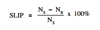
Motor Slip Formula

where

NS = synchronous speed (rpm)
NR = rotor speed (rpm)

The speed of the rotating magnetic field or synchronous speed of a motor can be found by using below Equation.
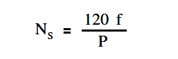
synchronous speed of a motor

where

NS = speed of rotating field (rpm)
f = frequency of rotor current (Hz)
P = total number of poles

Example:

A two pole, 60 Hz AC induction motor has a full load speed of 3554 rpm. What is the percent slip at full load?

Solution:

Synchronous speed:

synchronous speed of a motor

NS = (120 x 60 )/2

NS = 3600 rpm

Slip:

Motor Slip Formula

Slip = { (3600 – 3554) / 3600 } 100

Slip = 1.3 %

Don't Miss Our Updates
Be the first to get exclusive content straight to your email.
We promise not to spam you. You can unsubscribe at any time.
Invalid email address
You've successfully subscribed !

Continue Reading

Voltage Divider
Synchronous Motors
Classification of Transformers
Low Voltage Protection (LVP) and Low Voltage Release (LVR)
Resistance in Parallel Circuits
Series Short Circuit Faults
Share This Article
Facebook Whatsapp Whatsapp LinkedIn Copy Link
Share
Leave a Comment

Leave a Reply Cancel reply

Your email address will not be published. Required fields are marked *

Stay Connected

128.3kFollowersLike
69.1kFollowersFollow
210kSubscribersSubscribe
38kFollowersFollow

Categories

Explore More

Unbalanced 3 Phase Loads
Wiring Diagram
Compound Generators
Calculate Power in Series RC Circuit
DC Motor Connections
Types of Capacitors
Methods of Producing Voltage (Electricity)
High Voltage Circuit Breaker Principle

Keep Learning

Voltage Drop in a Series Circuit

Series Resistance

Ammeter with Shunt

Ammeter

What is electrical transformer

Transformer Impedance Ratio

Induced EMF

Magnetic Circuits

Compounded DC Generator

Parallel AC Generators

Schematic Diagram

Schematic Diagram

Calculate Power in Series RCL Circuit

Calculate Power in Series RCL Circuit

Shorted Parallel Circuit

Parallel Short Circuit Faults

Learn More

Fieldbus Analog Input Function Block

Bubble Tube Level measurement

Bubble Tube Level Measurement Principle

caliper metrology tool

An Overview of Metrology Tools for CNC Machining

Piston Check Valve

What is Piston Check Valve ?

Linear Heat Detector Working Principle

What are Linear Heat Detectors?

Split Range Control for Temperature Control Application

Split Range Control Working Principle

Industrial Automation Sales and Marketing Tools

Industrial Automation Sales and Marketing Tools

Electrical Machines Objective Questions

Electrical Machines MCQ Series 19

Menu

  • About
  • Privacy Policy
  • Copyright

Quick Links

  • Learn PLC
  • Helping Hand
  • Part Time Job

YouTube Subscribe

Follow US
All rights reserved. Reproduction in whole or in part without written permission is prohibited.
Welcome Back!

Sign in to your account

Username or Email Address
Password

Lost your password?