A low-voltage circuit breaker is one which is suited for circuits rated at 600 volts or lower. One of the most commonly used low-voltage air circuit breakers is the molded case circuit breaker (below Figure).
Circuit Breaker
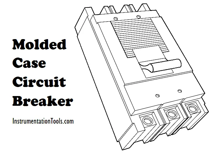
Figure : Molded Case Circuit Breaker
A cutaway view of the molded case circuit breaker is shown in below Figure.
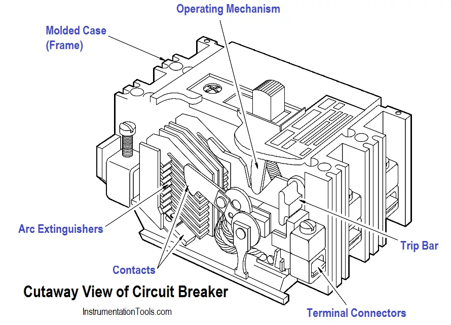
Figure : Cutaway View of Molded Case Circuit Breaker
A circuit can be connected or disconnected using a circuit breaker by manually moving the operating handle to the ON or OFF position. All breakers, with the exception of very small ones, have a linkage between the operating handle and contacts that allows a quick make (quick break contact action) regardless of how fast the operating handle is moved.
The handle is also designed so that it cannot be held shut on a short circuit or overload condition. If the circuit breaker opens under one of these conditions, the handle will go to the trip-free position. The trip-free position is midway between the ON and OFF positions and cannot be re-shut until the handle is pushed to the OFF position and reset.
A circuit breaker will automatically trip when the current through it exceeds a pre-determined value. In lower current ratings, automatic tripping of the circuit breaker is accomplished by use of thermal tripping devices. Thermal trip elements consist of a bimetallic element that can be calibrated so that the heat from normal current through it does not cause it to deflect.
An abnormally high current, which could be caused by a short circuit or overload condition, will cause the element to deflect and trip the linkage that holds the circuit breaker shut. The circuit breaker will then be opened by spring action. This bimetallic element, which is responsive to the heat produced by current flowing through it, has an inverse-time characteristic. If an extremely high current is developed, the circuit breaker will be tripped very rapidly.
For moderate overload currents, it will operate more slowly. Molded case breakers with much larger current ratings also have a magnetic trip element to supplement the thermal trip element. The magnetic unit utilizes the magnetic force that surrounds the conductor to operate the circuit breaker tripping linkage.
When the separable contacts of an air circuit breaker are opened, an arc develops between the two contacts. Different manufacturers use many designs and arrangements of contacts and their surrounding chambers. The most common design places the moving contacts inside of an arc chute.
The construction of this arc chute allows the arc formed as the contacts open to draw out into the arc chute. When the arc is drawn into the arc chute, it is divided into small segments and quenched. This action extinguishes the arc rapidly, which minimizes the chance of a fire and also minimizes damage to the breaker contacts.
Check Out : Circuit Breaker Animation
Molded case circuit breakers come in a wide range of sizes and current ratings. There are six frame sizes available: 100, 225, 400, 600, 800, and 2,000 amps. The size, contact rating, and current interrupting ratings are the same for all circuit breakers of a given frame size. The continuous current rating of a breaker is governed by the trip element rating. The range of voltage available is from 120 to 600 volts, and interrupting capacity ranges as high as 100,000 amps.
Much larger air circuit breakers are used in large commercial and industrial distribution systems. These circuit breakers are available in much higher continuous current and interrupting ratings than the molded case circuit breaker. Breakers of this type have current ratings as high as 4,000 amps, and interrupting ratings as high as 150,000 amps.
Most large air circuit breakers use a closing device, known as a “stored energy mechanism,” for fast, positive closing action. Energy is stored by compressing large powerful coil springs that are attached to the contact assembly of a circuit breaker. Once these springs are compressed, the latch may be operated to release the springs, and spring pressure will shut the circuit breaker. Circuit breaker closing springs may be compressed manually or by means of a small electric motor. This type of circuit breaker can be classified as either a manually- or electrically-operated circuit breaker.
When a large air circuit breaker is closed, the operating mechanism is latched. As the circuit breaker is closed, a set of tripping springs, or coils, are compressed, and the circuit breaker may then be tripped by means of a trip latch. The trip latch mechanism may be operated either manually or remotely by means of a solenoid trip coil.
As previously stated, circuit breakers may be operated either manually or electrically. Electrically-operated circuit breakers are used when circuit breakers are to be operated at frequent intervals or when remote operation is required.
When the electrically-operated stored energy circuit breaker is tripped, the spring is recharged by the spring charging motor so that the breaker is ready for the next closing operation. The manually-operated circuit breaker closing springs are normally compressed by a hand crank just prior to operation of the breaker.
The below Figure shows a large air circuit breaker which is classified as a manually-operated stored energy circuit breaker. The closing springs are compressed by pulling downward on the large operating handle on the front of the breaker. Closing this circuit breaker is accomplished manually by depressing the small closing lever. Tripping this circuit breaker is done by means of the tripping lever, located at the bottom front of the breaker.
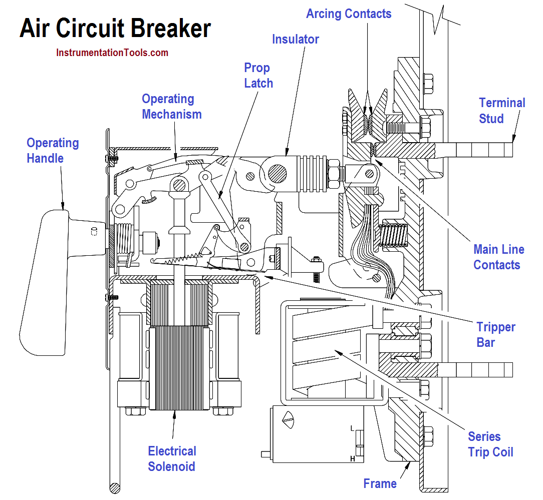
Figure : Large Air Circuit Breaker