Inst ToolsInst ToolsInst Tools
  • Courses
  • Automation
    • PLC
    • Control System
    • Safety System
    • Communication
    • Fire & Gas System
  • Instrumentation
    • Design
    • Pressure
    • Temperature
    • Flow
    • Level
    • Vibration
    • Analyzer
    • Control Valve
    • Switch
    • Calibration
    • Erection & Commissioning
  • Interview
    • Instrumentation
    • Electrical
    • Electronics
    • Practical
  • Q&A
    • Instrumentation
    • Control System
    • Electrical
    • Electronics
    • Analog Electronics
    • Digital Electronics
    • Power Electronics
    • Microprocessor
  • Request
Search
  • Books
  • Software
  • Projects
  • Process
  • Tools
  • Basics
  • Formula
  • Power Plant
  • Root Cause Analysis
  • Electrical Basics
  • Animation
  • Standards
  • 4-20 mA Course
  • Siemens PLC Course
Reading: Voltage Polarity and Current Direction
Share
Notification Show More
Font ResizerAa
Inst ToolsInst Tools
Font ResizerAa
  • Courses
  • Design
  • PLC
  • Interview
  • Control System
Search
  • Courses
  • Automation
    • PLC
    • Control System
    • Safety System
    • Communication
    • Fire & Gas System
  • Instrumentation
    • Design
    • Pressure
    • Temperature
    • Flow
    • Level
    • Vibration
    • Analyzer
    • Control Valve
    • Switch
    • Calibration
    • Erection & Commissioning
  • Interview
    • Instrumentation
    • Electrical
    • Electronics
    • Practical
  • Q&A
    • Instrumentation
    • Control System
    • Electrical
    • Electronics
    • Analog Electronics
    • Digital Electronics
    • Power Electronics
    • Microprocessor
  • Request
Follow US
All rights reserved. Reproduction in whole or in part without written permission is prohibited.
Inst Tools > Blog > Electrical Theory > Voltage Polarity and Current Direction

Voltage Polarity and Current Direction

Last updated: July 23, 2018 2:55 pm
Editorial Staff
Electrical Theory
1 Comment
Share
2 Min Read
SHARE

Before understanding the laws associated with complex DC circuit analysis, the importance of voltage polarity and current direction must be understood. This article will introduce the polarities and current direction associated with DC circuits.

Conventional and Electron Flow

The direction of electron flow is from a point of negative potential to a point of positive potential. The direction of positive charges, or holes, is in the opposite direction of electron flow. This flow of positive charges is known as conventional flow.

All of the electrical effects of electron flow from negative to positive, or from a high potential to a lower potential, are the same as those that would be created by flow of positive charges in the opposite direction; therefore, it is important to realize that both conventions are in use, and they are essentially equivalent. In this manual, the electron flow convention is used.

Polarities

All voltages and currents have polarity as well as magnitude. In a series circuit, there is only one current, and its polarity is from the negative battery terminal through the rest of the circuit to the positive battery terminal. Voltage drops across loads also have polarities.

The easiest way to find these polarities is to use the direction of the electron current as a basis. Then, where the electron current enters the load, the voltage is negative (Figure 31). This holds true regardless of the number or type of loads in the circuit. The drop across the load is opposite to that of the source. The voltage drops oppose the source voltage and reduce it for the other loads. This is because each load uses energy, leaving less energy for other loads.
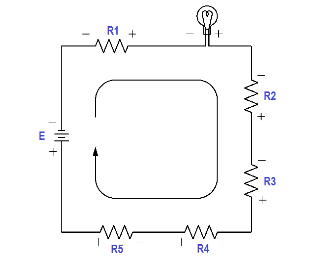
Voltage Polarities

Figure 31 Voltage Polarities
Don't Miss Our Updates
Be the first to get exclusive content straight to your email.
We promise not to spam you. You can unsubscribe at any time.
Invalid email address
You've successfully subscribed !

Continue Reading

Power in Balanced 3 Phase Loads
Apparent Power, True Power, Reactive Power & Total Power
Electrical Wiring Terminology
Batteries Theory
Reading Electrical Schematics
Circuit Breaker Control Circuit
Share This Article
Facebook Whatsapp Whatsapp LinkedIn Copy Link
Share
1 Comment
  • m.seibel says:
    May 6, 2021 at 1:19 am

    This would be more to the point in answering a simple query.
    ‘The direction of electron flow is from negative potential to positive potential.
    The direction of conventional flow is positive potential to negative potential’.

    Conventional and Electron Flow (present post)
    The direction of electron flow is from a point of negative potential to a point of positive potential. The direction of positive charges, or holes, is in the opposite direction of electron flow. This flow of positive charges is known as conventional flow.

    Reply

Leave a Reply Cancel reply

Your email address will not be published. Required fields are marked *

Stay Connected

128.3kFollowersLike
69.1kFollowersFollow
210kSubscribersSubscribe
38kFollowersFollow

Categories

Explore More

Three Phase Transformer Connections
4-Wire, Three-Phase Delta Wiring System
Voltmeters
Single Phase AC Induction Motors
Inductive Time Constant
Three Phase AC Generators
Types of Batteries
Shunt-Wound Motor Operation

Keep Learning

Capacitors Connected in Parallel

Series and Parallel Capacitors

Carbon Atom

What is Electricity ?

Transformer Tap changer

Transformer Mutual Induction

Squirrel-Cage Induction Rotor

Induction Motor

Transformer voltage and turns ratio

Transformer Current Ratio

circuit breaker principle

What is a circuit breaker ?

Capacitive Time Constant for Charging Capacitor

Capacitive Time Constant

Generator Action in a Motor

What is Synchroscope ?

Learn More

Analog Electronics Objective Questions

Analog Electronics Objective Questions – Set 3

Wiring in PLC System

Wiring in a PLC Control Panel

Data Instance in PLC

Tia Portal – Different Instances of Calling a Function Block

Paddle Wheel Level Switch Principle

Paddle Wheel Level Switch Principle

Control Room Design Guidelines

Control Room Design Guidelines

Voting Logic in Safety Instrumented System (SIS)

Voting Logic in Safety Instrumented System (SIS)

PV Tracking in PID Controllers

What is PV Tracking ?

PLC Program for Counting Objects on Conveyor

PLC Program for Counting Moving Objects on Conveyor

Menu

  • About
  • Privacy Policy
  • Copyright

Quick Links

  • Learn PLC
  • Helping Hand
  • Part Time Job

YouTube Subscribe

Follow US
All rights reserved. Reproduction in whole or in part without written permission is prohibited.
Welcome Back!

Sign in to your account

Username or Email Address
Password

Lost your password?