Safety systems are implemented to reduce operational risks and improve process safety; however, there are instances when some signals of this system shall be bypassed or overridden. Safety Signal Overrides usually appeared in two modes: Maintenance Override and Process Override. Maintenance Override is used mainly for Device/ Instrument repair or proof testing, while Process Override is used mainly for bypassing or changing process routes or equipment due to process conditions requirements (as an example, not readiness status of some equipment or process conditions during plant startup).
Override Safety Signal

Applying safety signal override (in any case) to be done based on some requirements mentioned in IEC 61511 Standard; however, implementing relevant facilities to obey rules and standard requirements, further to producing best operation performances via using Combined Process Control and Safety Systems tools and facilities is the design engineering skills/ arts. Using some implemented practices may help I&C design engineers to improve such implementations in their future jobs. In this article, we will review one of the good practices in this regard to study some Safety Signal Override aspects.
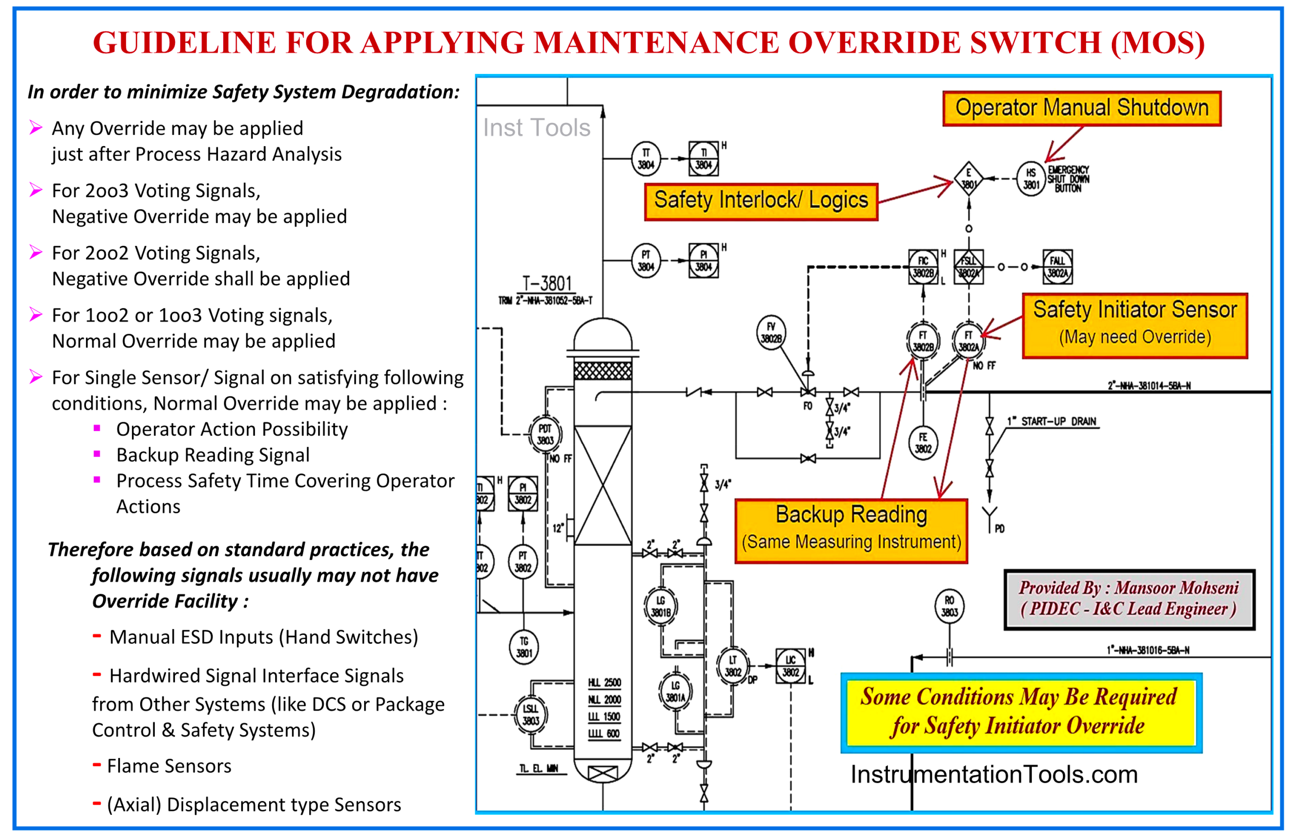
Figure 1: Guideline for Applying Maintenance Override Switch (MOS).
IEC 61511 as Basic Safety Standard Requirement for Applying Signal Override
IEC61511 is the main standard for describing the basic requirements and specifications of a Safety Instrumented System used in Process Plant Industries. Due to the great (and possibly critical) effects of overriding safety signals on degrading Safety Instrumented Systems (SIS), applying such facilities shall be done based on the mentioned standard.
Although the IEC 61511 explains some requirements and conditions of applying Safety Signal Override (see reference article) but however, it leaves some freedom to detail design engineers for how to implement such facilities due to available tools and technologies. This makes different observable ways and options in the actual implementation of such facilities by different companies, and some of them can be considered good practices. Of course, studying the good practices may help design engineers improve their current or future jobs.
PHA Requirements for Safety Signal Override
First of all, considering any Safety Signal Override shall be done after doing Process Hazard & Risk Analysis (Process H&RA) and studying the needs for applying any bypass or override, and the consequences risks, further to possible safeguarding measures (as described in clause 8 of IEC-61511 standard “Process H&RA”). The results of such Process H&RA studies shall be reflected in all relevant project documentations (like P&IDs, Cause & Effects Diagrams, Process Description Manuals …).
As an example, the general routine of considering Maintenance Override for Safety Signals shall be discussed, and the procedure/ guideline shall be defined for all general cases (and for any special cases, further clarifications or notes to be dedicatedly added).
Figure 1 shows made general guideline for Maintenance Override as:
- For 2oo3 Voting Signals, Negative Override may be applied
- For 2oo2 Voting Signals, Negative Override shall be applied
- For 1oo2 or 1oo3 Voting Signals, Normal Override may be applied
For a Single Sensor/ Signal on satisfying the following conditions, Normal Override may be applied:
- Operator Action Possibility
- Backup Reading Signal
- Process Safety Time Covering Operator Actions
Note: Normal Override means fixing the signal to “1”, and Negative Override means fixing the signal to “0”.
All Process Overrides shall be studied exactly too, and again, the results shall be reflected in all relevant project documentations accordingly. It is reminded that Maintenance Override is used mainly for Device/ Instrument repair or proof testing, while Process Override is used mainly for bypassing or changing process routes or equipment due to process conditions requirements (as an example, not readiness status of some equipment or process conditions during plant startup).
Further to the guidelines mentioned in Figure 1 clarifying the following items are required too:
- Maintenance Override usually will be activated (Enabled) and deactivated (Disabled) manually (by operator/ human action), while Process Override usually will be deactivated automatically (by elapsing the considered set time or by reaching normal process condition(s)).
- The considered set times for each Process Override case and the exact following actions shall be defined exactly.
- It is very important to discuss the quantity of simultaneous acceptable overrides and the exact limitations for any special cases (or interlocks).
- Force Override facility use in abnormal Process Operation Conditions and the possibility of using Maintenance Override in situ shall be studied too.
Switches for Enabling Override (MOS & POS)
For enabling Override facilities, some security switches shall be defined. Usually, these switches for Maintenance Override are called MOS, and for Process Override are called POS. The quantity, type (hardwire or software switch), and the access security level of these switches shall be shown or noted for special cases in relevant documents (such as P&IDs and Cause & Effects Diagrams), and accordingly, their action effects shall be defined and explained in descriptive documents (such as Procedures and Manuals).
Example of Applying Good Safety Signal Override
Now, let us review some aspects of an example of applying a good safety signal override. The following items are extracted from the (PIDEC) company practice, and of course, some more details of implementing, it cannot be explained here (and are confidential).
MOS Function Block
At the beginning of the Logic Diagram document, the MOS function block shall be defined for both digital and analog inputs, and then such function blocks will be inserted in all applicable cases (Figures 2,3, and 4). We can see that:
- The MOS function block will have effects on the action of the Input Signal throughout the Logic Diagram, and it does not have any effects on monitoring the actual real value of the Input Signal and the relevant Alarms.
- The status of MOS and overridden states of Signals (used throughout the Logic Diagram) will be monitored with relevant Alarms.
- Each Input Instrument may have just one MOS for all relevant states (different levels of AI Alarms as Low-Low, Low, High, High-High).
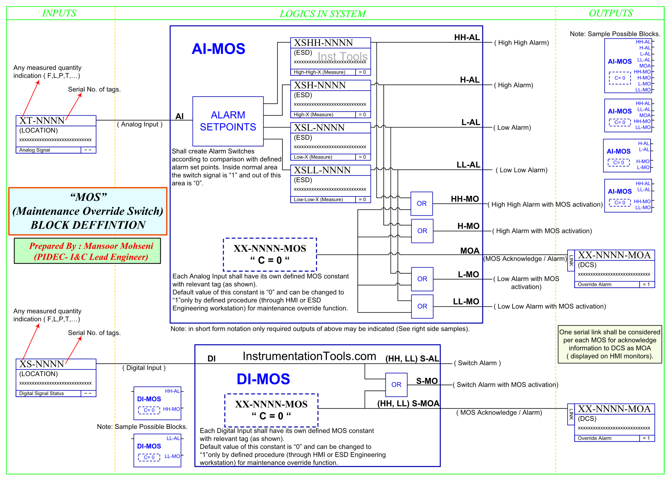
Figure 2: Defining Maintenance Override Switch (MOS) Function Block for Analog and Digital Inputs (AI, DI).
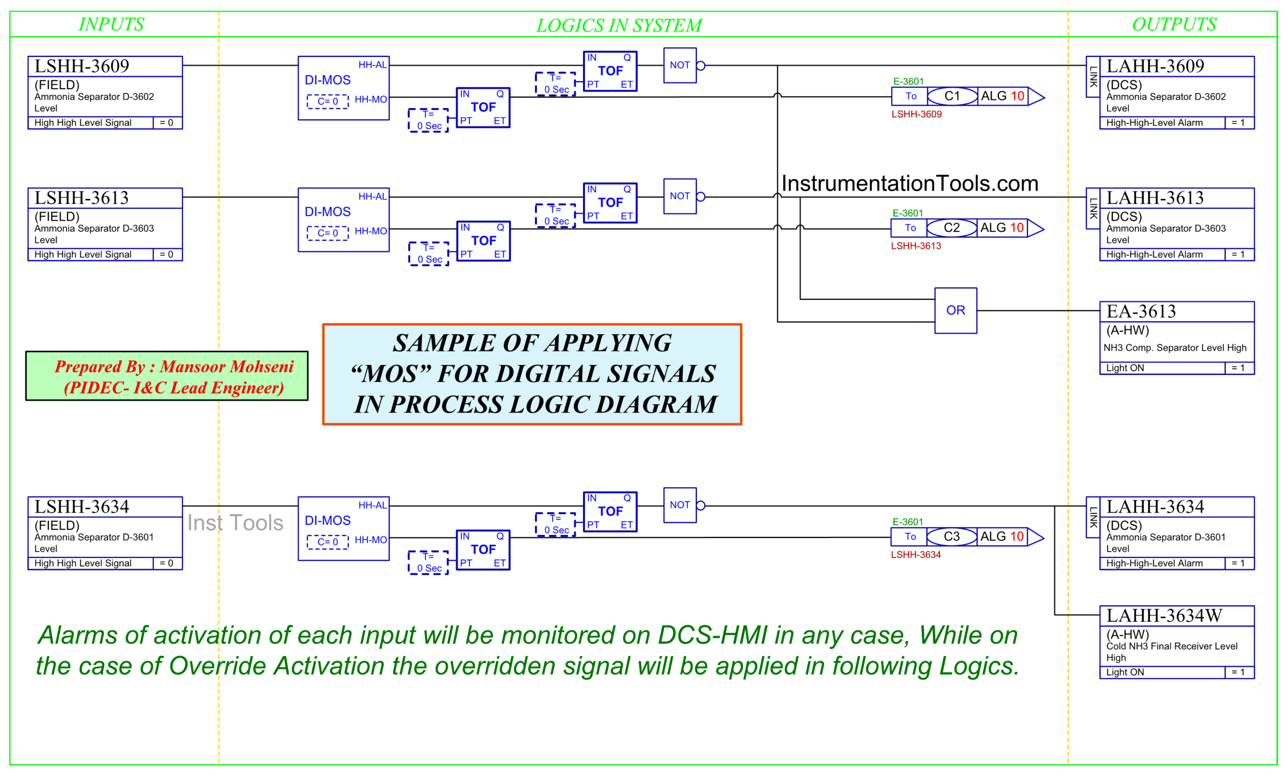
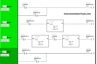
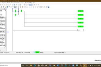
Figure 3: Sample of Applying MOS for Digital Input Signals in Process Logic Diagram.
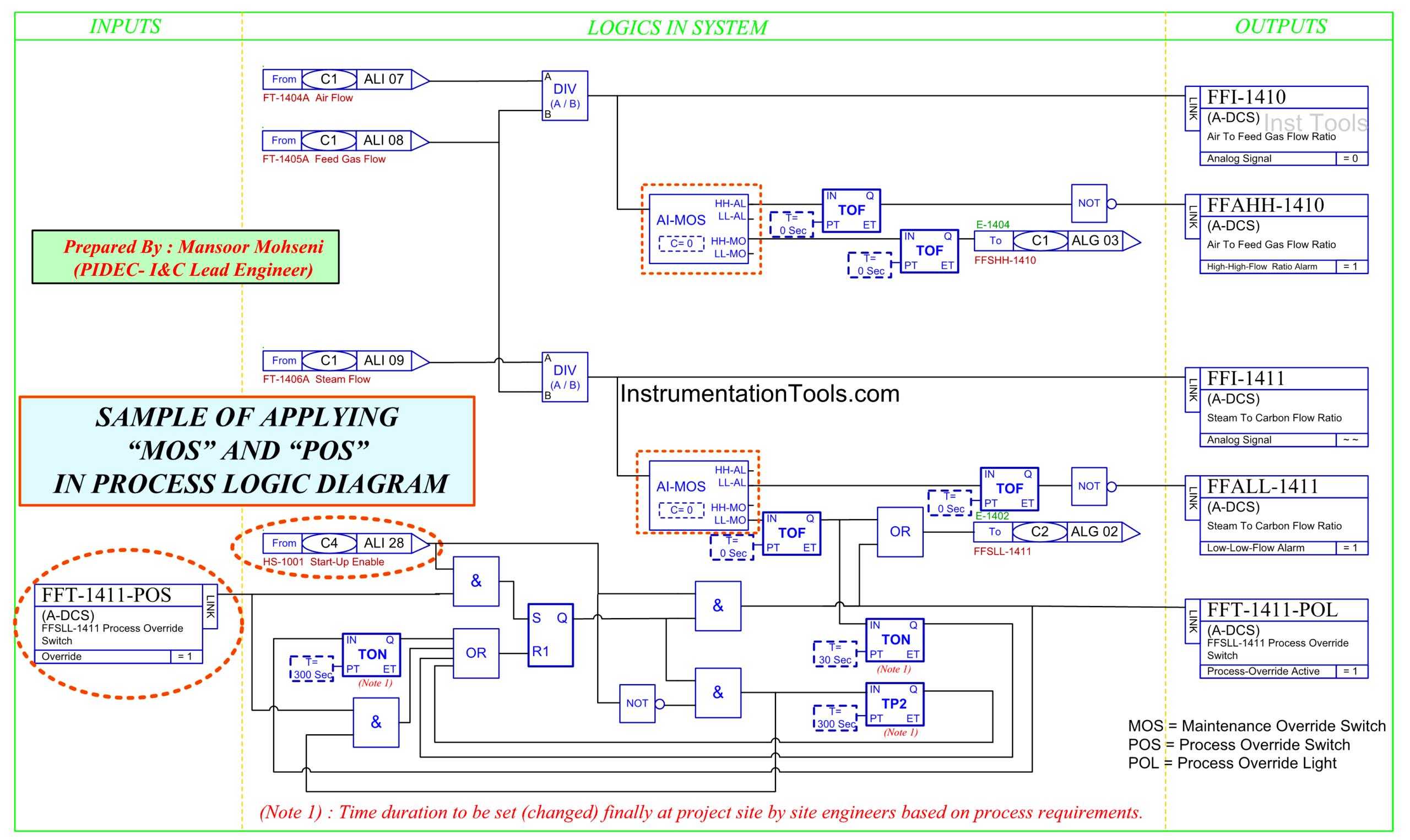
Figure 4: Sample of Applying MOS and POS in Process Logic Diagram.
- Each Input Signal will have its own dedicated MOS (defined constant) with the relevant tag number. The default value of this constant is “0” and can be changed to “1” only by a defined procedure (through HMI Graphic Page or ESD Engineering Workstation) for Maintenance Override Function.
- Each MOS activation will be done in conjunction with the Master MOS Enable (from Hardwired Console) and quantity limit check (not shown in the above figures).
- POS will be activated by some process conditions and an extra hardwired startup switch (startup enable switch shown in Figure 4), and will be removed (disabled) automatically by some considered timers.
- Each POS will have its own predefined Timers (based on Project Process Documents), which can be set separately/ exactly at the project site.
- The status of POS and relevant timers will be monitored on Operator Workstations (HMI).
- Some Safety Signals may have both MOS and POS (for different defined actions).
Master Enable Switch
There are some Master Enable Switches installed on the ESD Hardwired Console, which are covered during normal or special mode process plant operation from a security point of view (Figures 5 and 6).
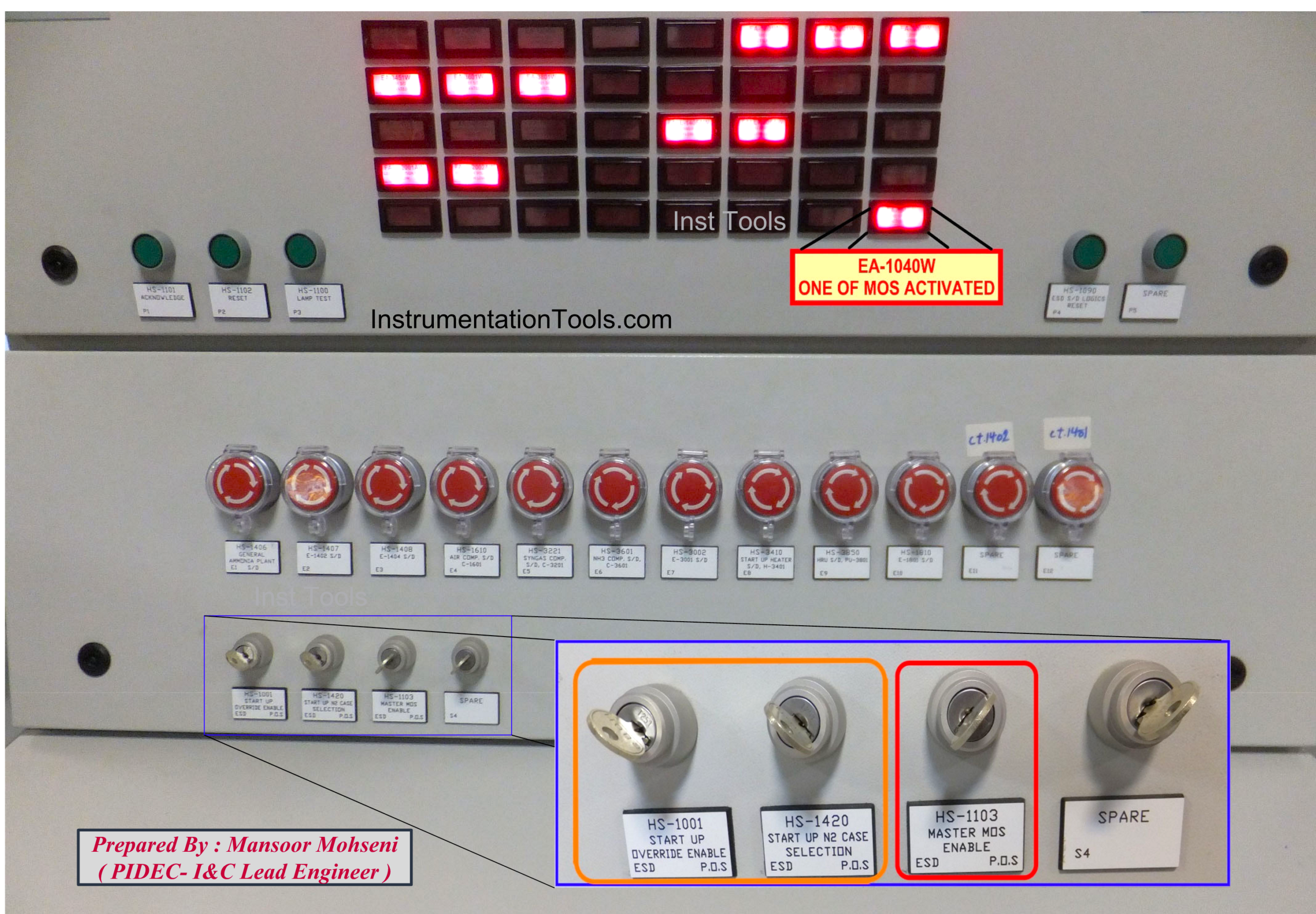
Figure 5: Master Enable (Startup/ Maintenance) switches on the ESD Hardwired Console.

Figure 6: Protection Covers for Not Removing Master Enable Keys.
MOS Critical Alarm indication on ESD Hardwired Console
ESD Hardwired Console, further to the inclusion of Hand Switches (for Emergency Shutdown, Master Enable Keys, Process Override Keys, Logic Resets, and Alarm Annunciation Sequence), is used for alerting/ indication of critical Process Alarms. One of the most critical alarms of the Process Plant is related to the indication for “at least one MOS activated”. Referring to Figures 5 through 9, we find that:
- The alarm indication of “at least one MOS activated” is located in a special position so that it can be detected or observed from far distances.
- The keys for critical actions (like Master Enables or POS) are not inserted in position during the normal Process Operation, and they are inserted just in special cases (or times).
- If Process Plant contains several independent Process Units, then for each Unit, one Master Enable Key shall be considered, and if the total Process Plant can be seen as one Process Function, then just one Master Enable Key is sufficient (as shown in the figures).
- In the case of a big project process plant, there is no need to consider different Unit Enable or even Override Enable per each Tag (a very small project), switches on the ESD Hardwired Console (as shown in the figures). However, for each special POS case, one switch may be considered.

Figure 7: ESD Hardwired Console contains Hand Switches and Annunciator for Critical Alarms.
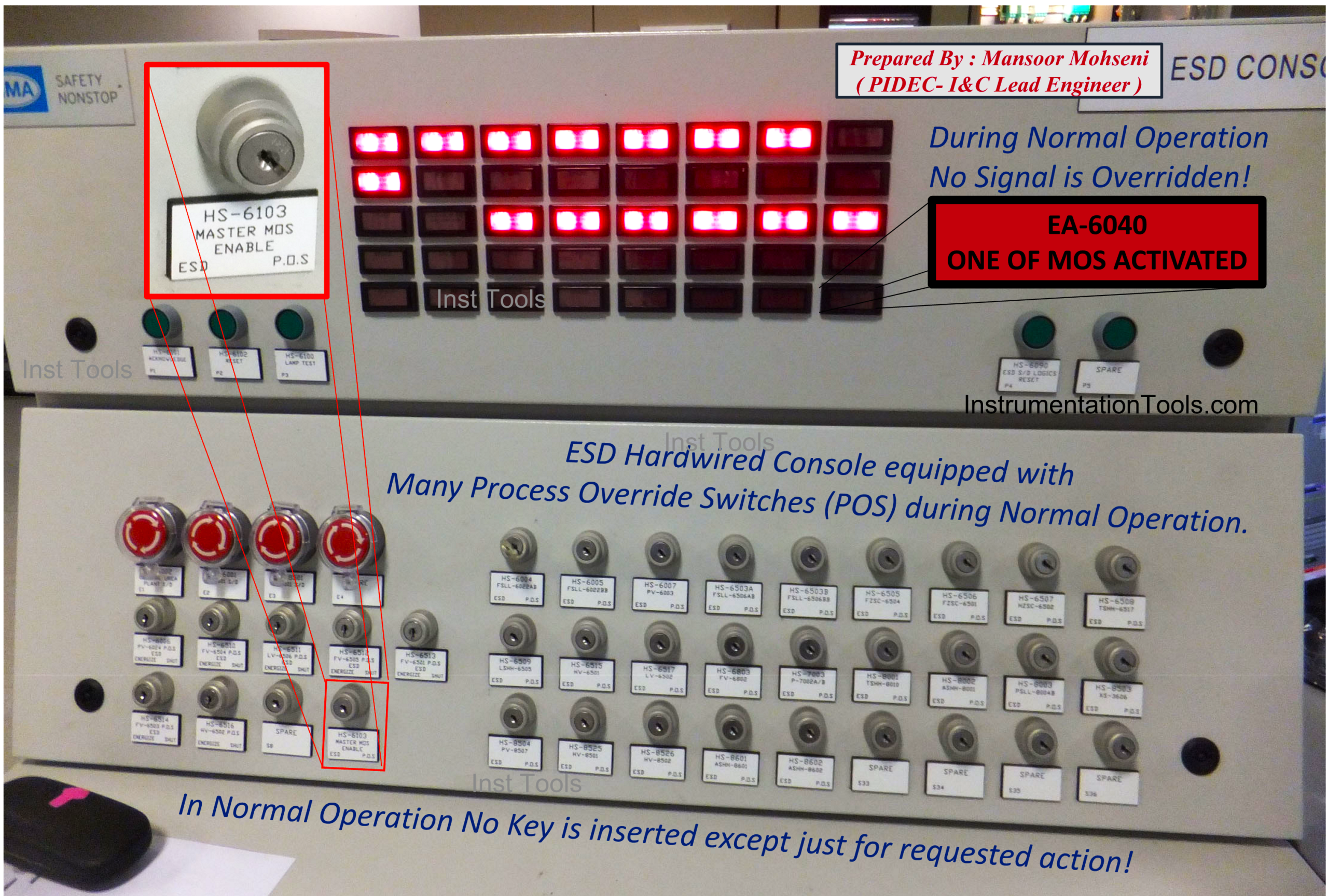
Figure 8: Dedicated Positions for Master Enable Key and “One of MOS Activated” Critical Alarm.

Figure 9: “One of MOS Activated” Critical Alarm can be detected and observed from far distances.
Override Indication on Process Graphic Pages of HMI
Process Plant operator shall be informed of any type of overrides via highlighted symbol indications on the graphic pages, and shall be trained to raise awareness on backup readings and further care in the case of an override being activated. By reviewing Figures 10 and 11, we may find that:
- A special dedicated symbol will appear for those signals that are overridden. Such a symbol indication will be more effective if it shows the disconnection and override state of the signal.
- Appearance of the signal override symbol (for each tag number) will be done via a dedicated feedback signal, which is received from the SIS Logic Diagram. On the other hand, for non-overridden signals (feedback), there will be no overridden signal that will appear.
- The override symbol does not have effects for monitoring the real state of the actual signal (if it is in normal or alarm state).
- No Interlock Logic Activation indication may help operators to see no action effects of Overridden Signals (of course, if it was not activated due to other causes may be even in other graphic pages).
- Process Operators shall be aware (and be trained) to find backup reading signals and take more care near the Overridden Signals.
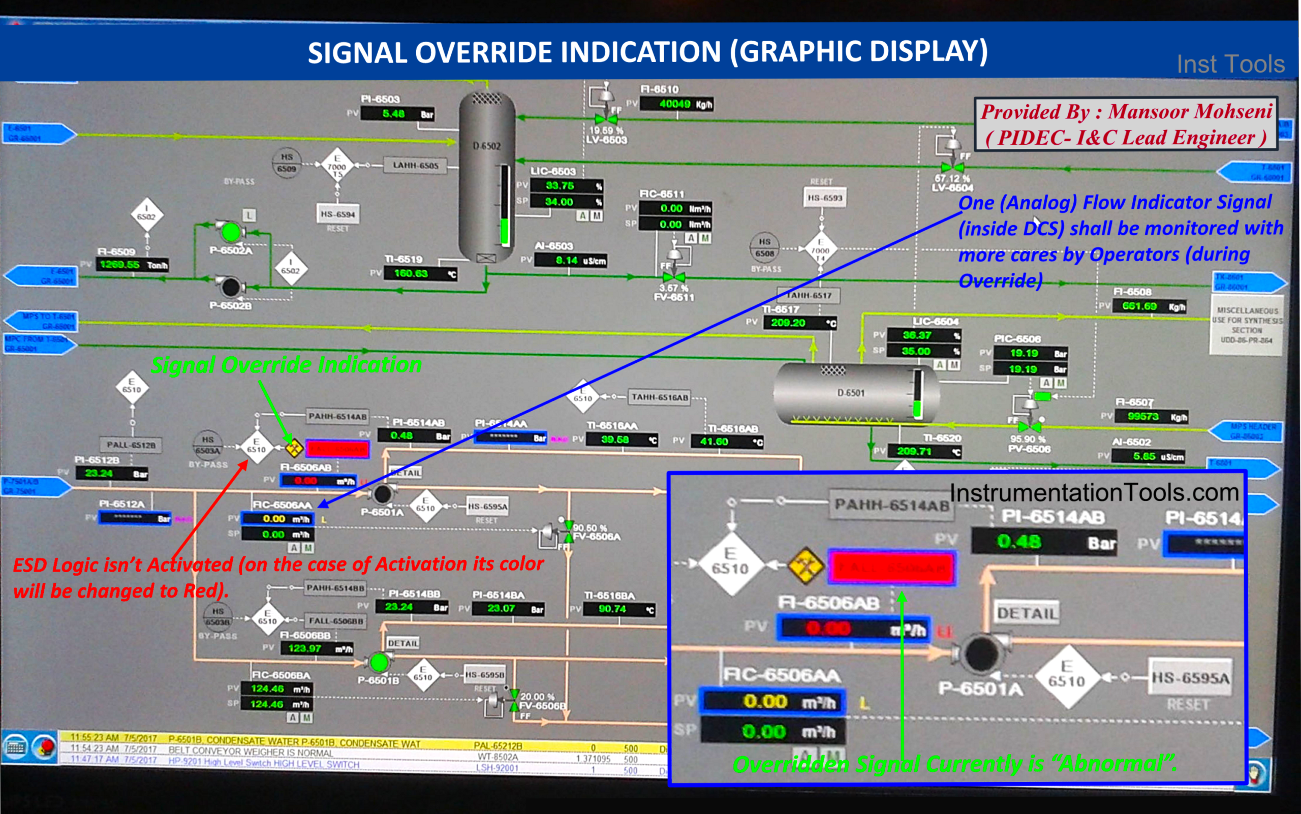
Figure 10: Signal Override Symbol Indication on Process Graphic Page.
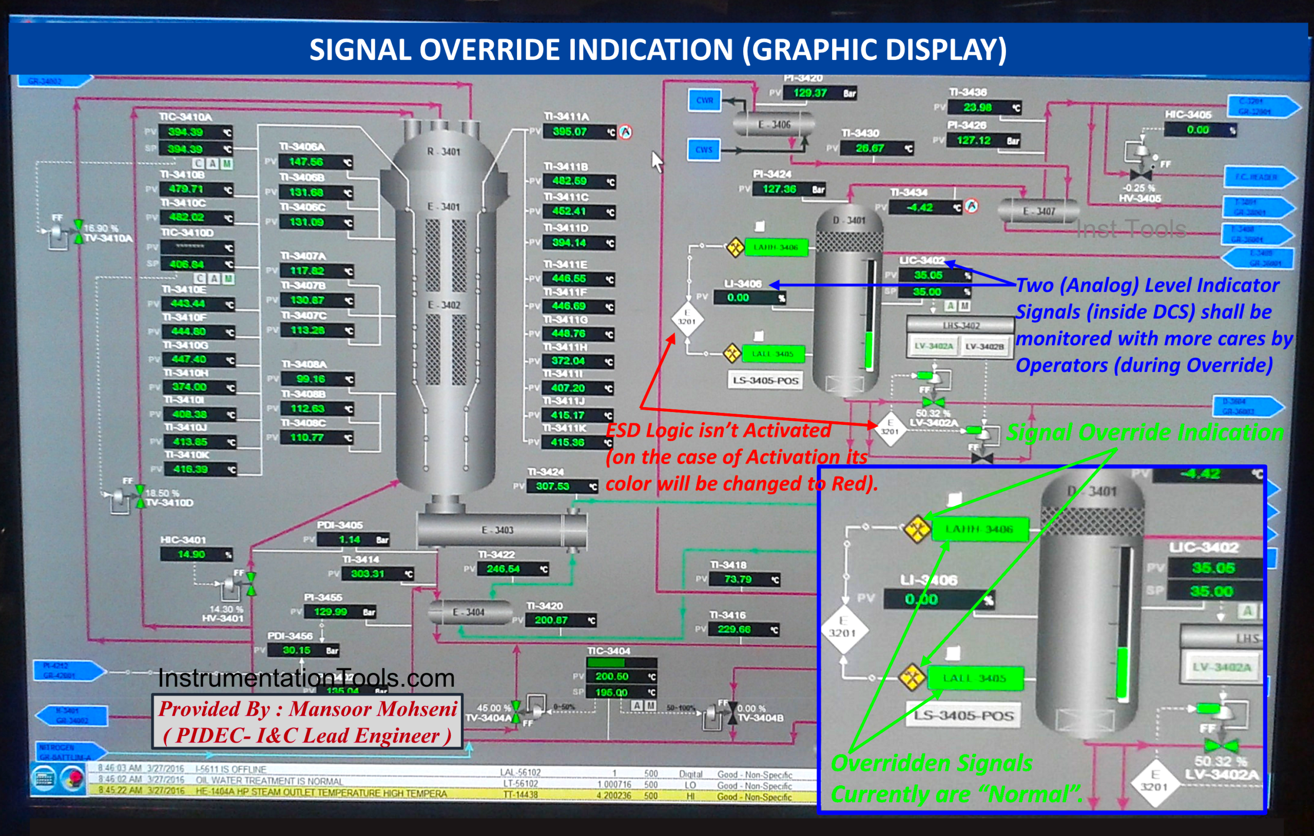
Figure 11: Signal Override Symbol Indication on Process Graphic Page.
SIS or ESD Interlock Logic Diagram & Override Overview Graphic Page
Providing one overview graphic page to show the general status of activation of SIS/ESD Interlock Logic Diagrams and master components of the Override Facility may be very helpful. Figures 12 and 13 show that:
- Generally, the status of each Activated (or Not Activated) Interlock Logic Diagram of SIS/ESD can be easily observed.
- Activation of Master Keys (Override / Startup Enable) can be easily observed.
- If at least one signal is overridden, it can be found by a dedicated status indication (which is the same as those that appear on the ESD Hardwired Console).
- The status of Process Override Switches and the current status of Overridden Signals, further to relevant Timer Settings, can be easily observed. Please notice in the figure, the POS symbol indication disappeared after finishing the relevant timer and showing that the signal is not overridden now (during the plant startup).
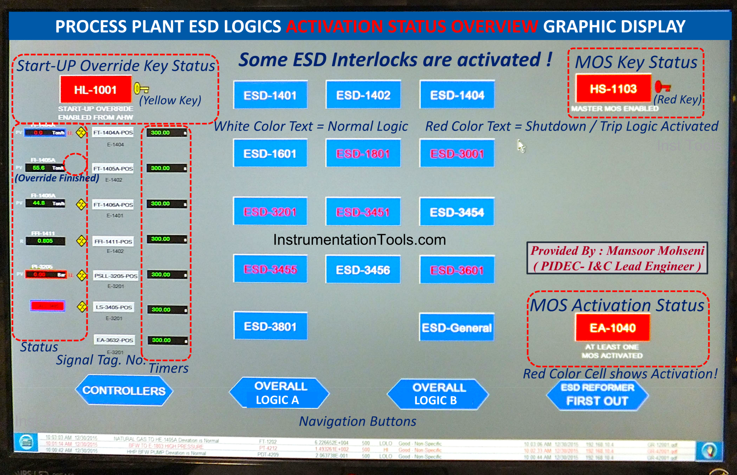
Figure 12: Overview Graphic Page for Monitoring SIS/ESD Interlock Logic Diagrams and Master Override Aspects.
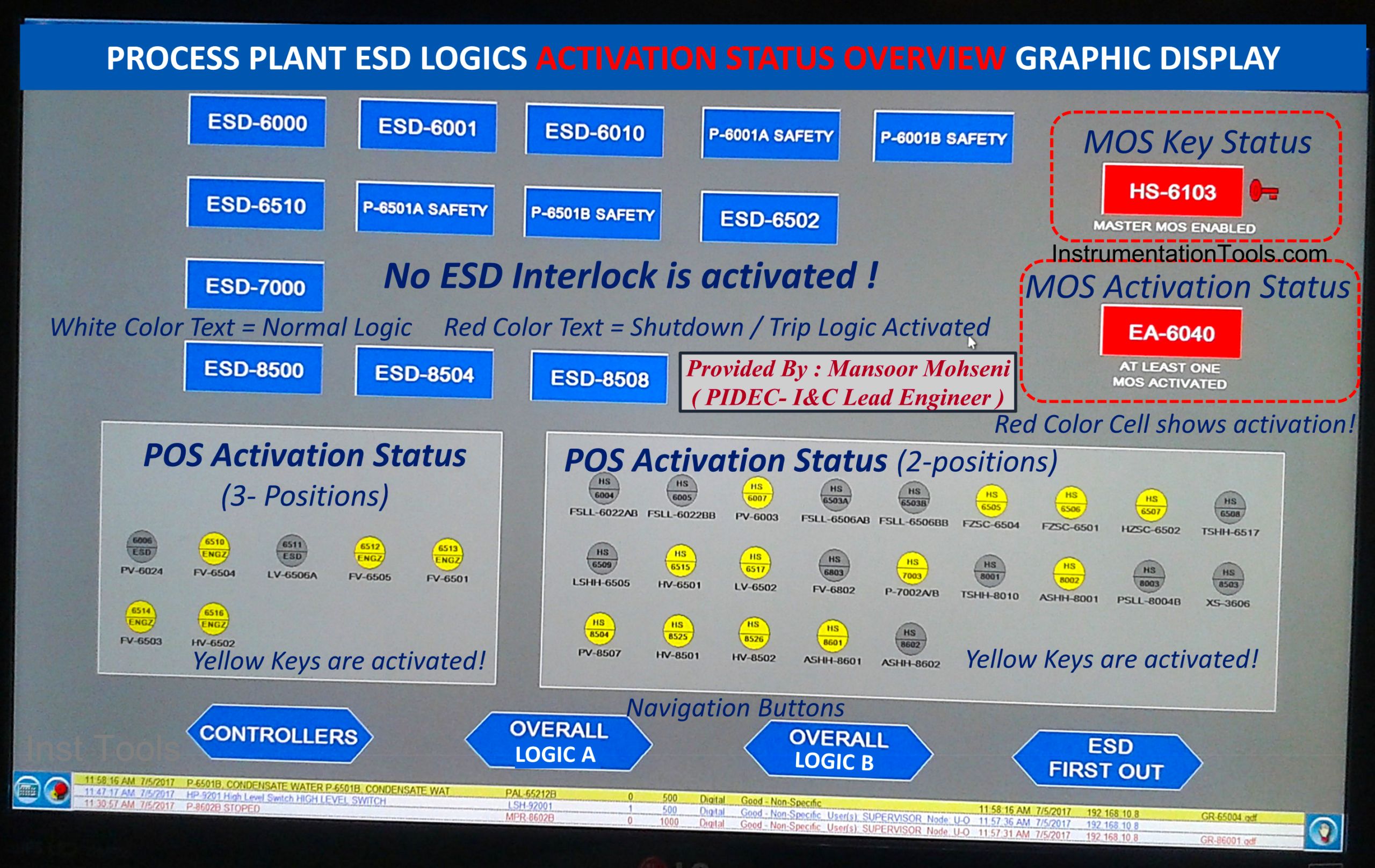
Figure 13: Overview Graphic Page for Monitoring SIS/ESD Interlock Logic Diagrams and Master Override Aspects (another process sample).
SIS or ESD Interlock Cause & Effects Diagram Monitoring
Signal Override facility shall be requested and monitored on Cause & Effects Table Diagrams too, since in such tables all signals of SIS/ESD Interlock Logic Diagrams appear. Figure 14 shows a sample of the monitoring Cause & Effects table of one Interlock and override facility request and indications.
- By clicking on SIS/ESD Logic Interlock, the relevant Cause and Effects Table will be opened.
- Each Input signal to the SIS/ESD Logic Interlock appears in separate rows containing the Tag Number with relevant Override facility Signals.
- Some Input Signals are not equipped with the Override Facility (due to the considered guideline rules).
- In this project (shown in Figure 13) Override Facility is provided so that it is possible to override multiple input signals of the interlock during the plant startup.
- In the shown case, some inputs are overridden (and may not activate the Logic Interlock), while Logic Interlock is activated due to signals that are not overridden (or do not have an Override facility).
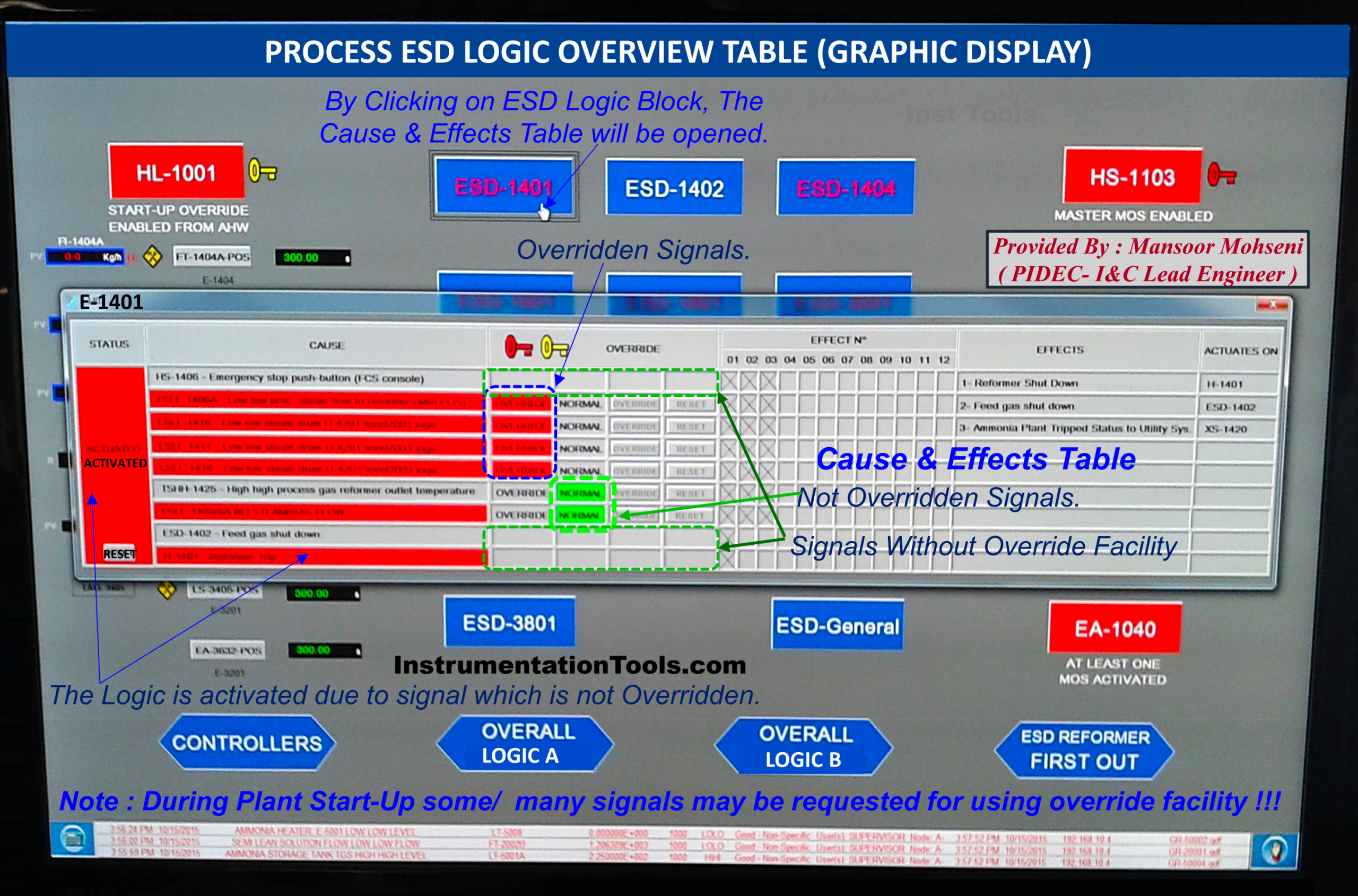
Figure 14: Graphic for Monitoring SIS/ESD Interlock Cause & Effects Diagram and Maintenance Override Aspects.
Overall SIS or ESD Interlock Logic Diagram Monitoring
Some Process Plants have the facility to provide a single graphic page as an Overview of SIS/ESD Interlock Logic Diagrams and Monitoring. In such cases, this graphic page should also include the Override facility aspects. Figure 15 shows a sample of such a graphic page, and we can find that:
- A hierarchical sequence of Interlock Logic Diagrams is shown in such a graphic page.
- All shown signals and relevant symbols will have the facility of dynamic color change based on the relevant status.
- Activation (enabling state) of override switches (MOS, POS) has a dynamic color change facility, too.
- Elapsed Time of Timers can be monitored, and so Process operators will be aware of the remaining time of each timer (for doing any required actions).
- The shown sequence of Logic Diagrams is provided by receiving signal status of Package Controls (inside package battery limits) with their interaction with Process Plant SIS/ESD System.
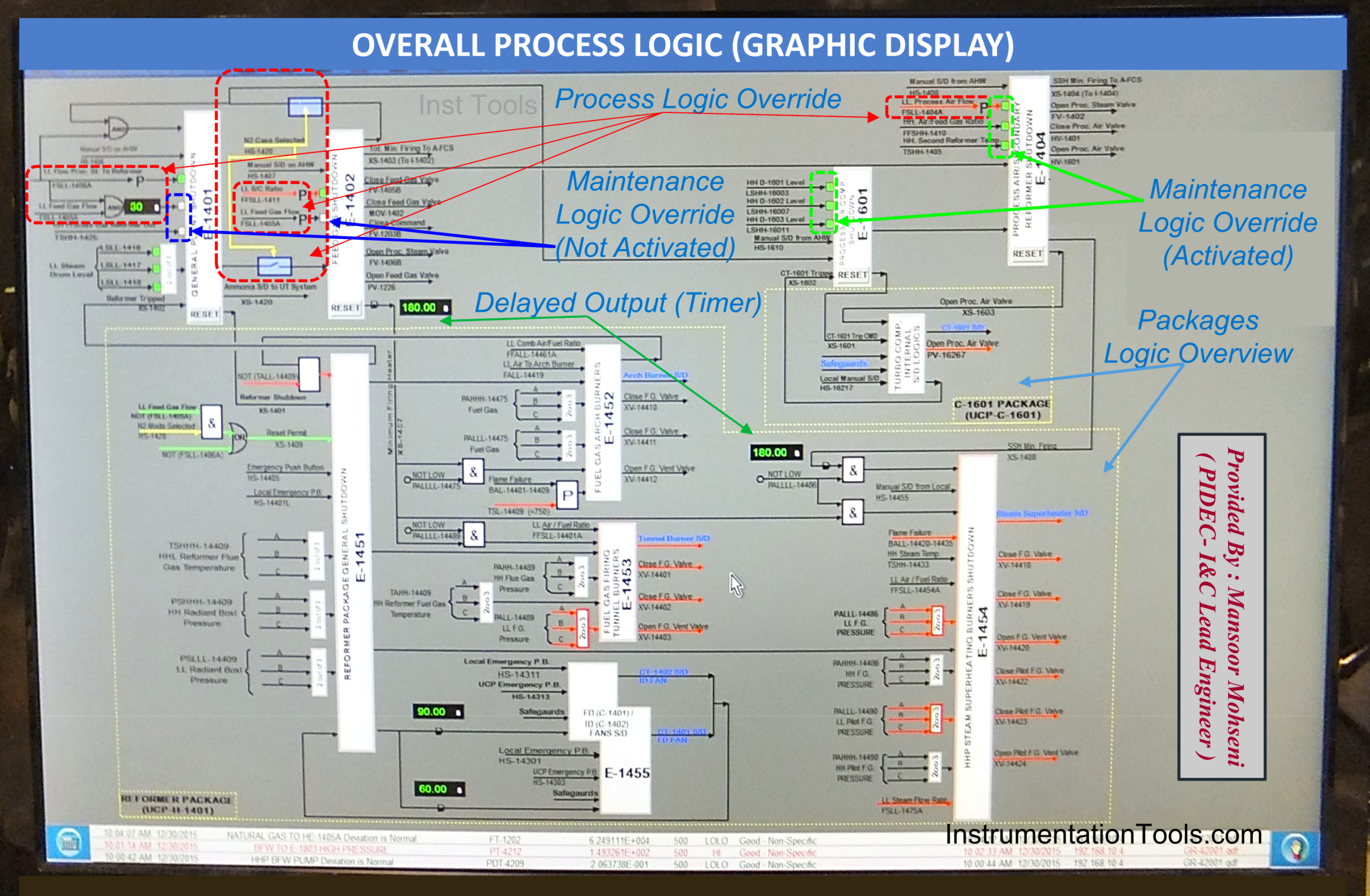
Figure 15: Overall Process Logic Diagram graphic Page includes the status of Override Switches (MOS, POS) and relevant functions.
References:
- Safety Function Bypass or Override
- IEC 61511 Standard for Bypass & Override
- Types of Implementing Safety Signal Bypass
- Force Versus Override for Safety Signal Bypass
- Safety Bypass Management System