This article discusses the “Loss in Weight Liquid System” often also called liquid filler or dosing pump using CX-Programmer Omron PLC Software. This PLC system is used for the process of filling liquid into a tank with a high level of accuracy. The system features two tanks: one for storage and the other for measuring the liquid. Its operation principle is based on the gradual and measurable weight reduction of the filled storage tank.
Program Objective
The PLC program uses 3 buttons:
- The PB_START button (0.00) is used to turn ON the system.
- The PB_STOP button (0.01) is used to turn OFF the system.
- The START_FILL button (0.02) is used to start the filling process on Tank-2.
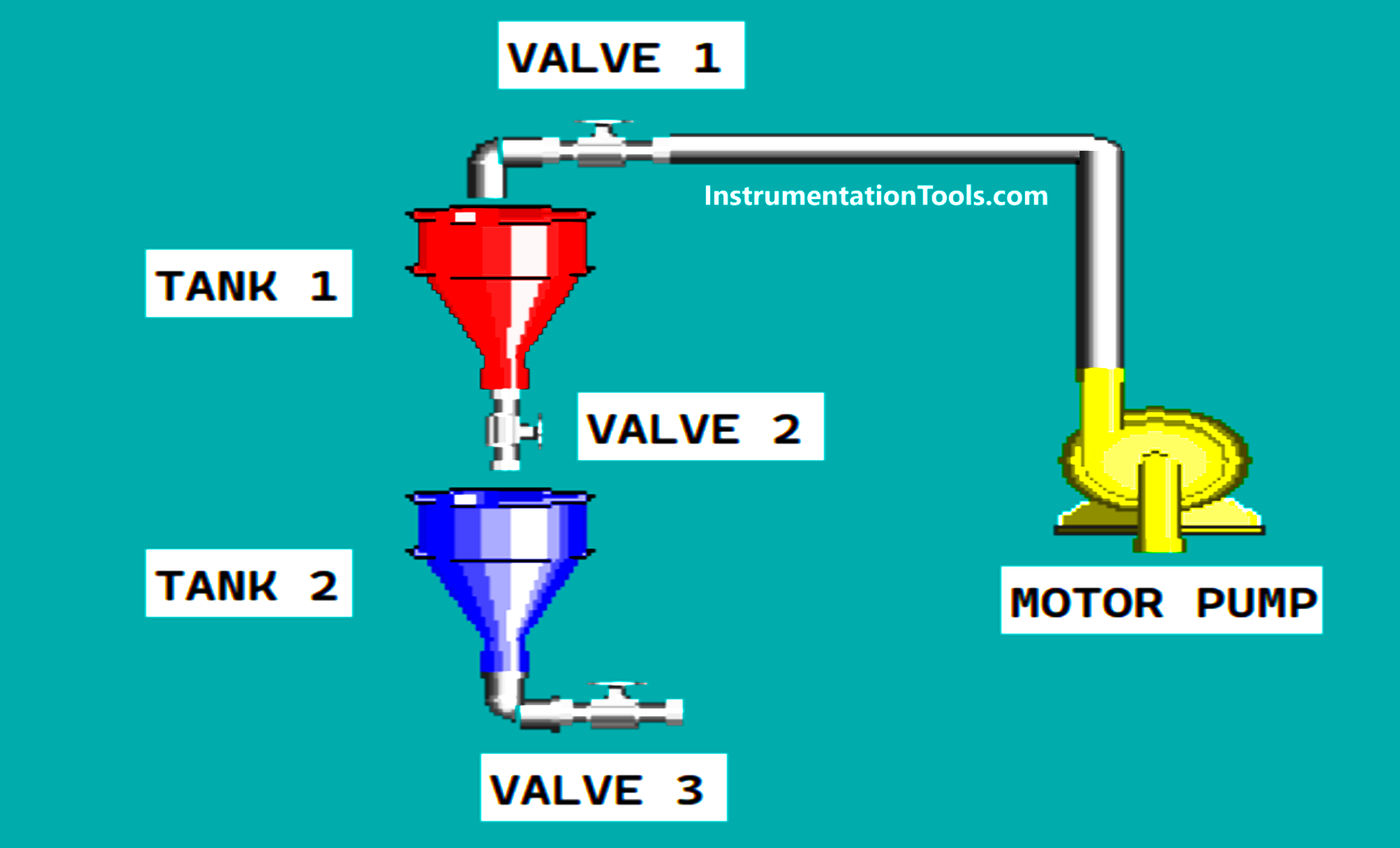
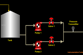
The “Loss in Weight Liquid” system has 2 tanks, Tank-1 is used for storage and Tank-2 is used to measure liquid contents. This system will reduce liquid measurably from Tank-1 to Tank-2 and drain the liquid contents from Tank-2.
This system only Starts if the Minimum “Set value” liquid content of Tank-1 has been Set (the value given must not be equal to zero).
Sequence-1 is the Tank 1 Filling Process
The Tank-1 Filling process will be carried out if the Liquid content of Tank-1 is below the Minimum “Set value” limit.
VALVE_1 (100.00) will OPEN first, 2 seconds after that the MOTOR_PUMP (100.01) will be ON and fill liquid into Tank-1.
When the liquid content reaches the Maximum limit (100 liters), MOTOR_PUMP (100.01) will be OFF and VALVE_1 (100.00) will CLOSE.
The Tank-1 Filling process will be carried out again if the Liquid content from Tank-1 is below the Minimum “Set value” limit.
Sequence-2 is the Tank 2 Filling Process
Before the Tank-2 Filling Process is carried out, the Maximum “Set value” limit for the liquid content of Tank-2 must be Set.
The Tank-2 Filling process will only be carried out when the START_FILL (0.02) button is Pressed.
VALVE_2 (100.02) will OPEN to drain liquid from Tank-1 to Tank-2, when Tank-2 has been filled with liquid according to the “Set value” VALVE_2 (100.02) will CLOSE.
Sequence-3 is the Drain Process
2 seconds after the Filling Tank-2 process is complete, the Drain process will be carried out. The Drain process aims to remove the liquid contents from Tank 2.
VALVE_3 (100.03) will OPEN to drain the liquid contents from Tank-2. VALVE_3 (100.03) will CLOSE again when Tank-2 is empty.
PLC IO List
| Comment | Input (I) | Output (Q) | Memory Word | Memory Bits | Timer |
| PB_START | 0.00 | ||||
| PB_STOP | 0.01 | ||||
| START_FILL | 0.02 | ||||
| VALVE_1 | 100.00 | ||||
| MOTOR_PUMP | 100.01 | ||||
| VALVE_2 | 100.02 | ||||
| VALVE_3 | 100.03 | ||||
| TIMER_1 | T0000 | ||||
| TIMER_2 | T0001 | ||||
| SYSTEM_ON | W0.00 | ||||
| IR_CUTOFF1 | W0.01 | ||||
| IR_CUTOFF2 | W0.02 | ||||
| IR_VALVE3 | W0.03 | ||||
| SV_TANK1 | D0 | ||||
| PV_TANK1 | D1 | ||||
| SV_TANK2 | D10 | ||||
| PV_TANK2 | D11 |
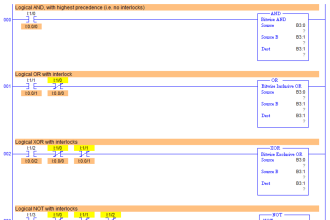
Dosing Pump PLC Logic
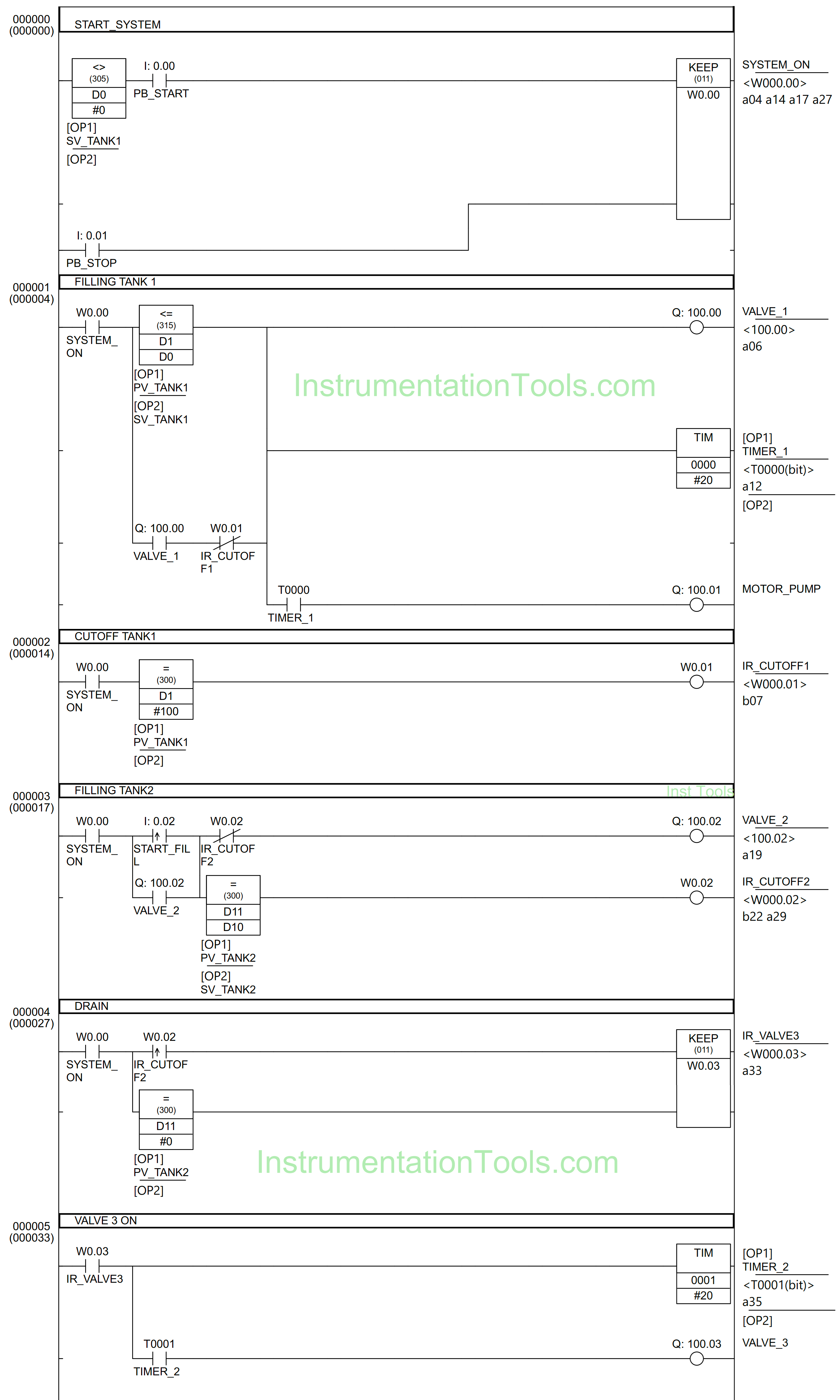
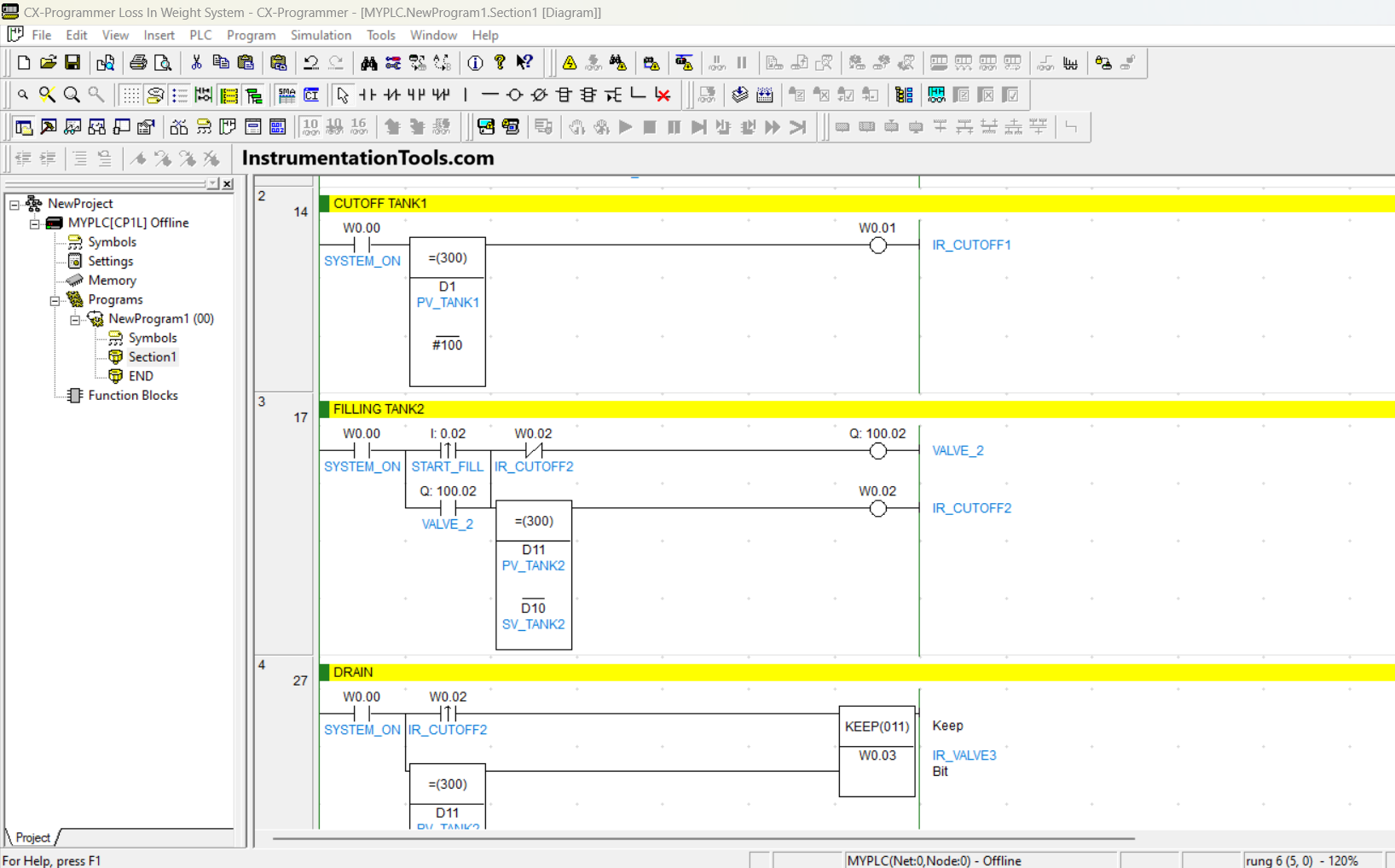
RUNG 0 (START SYSTEM)
In this Rung, when the memory word SV_TANK1 (D0) is not equal to zero “0” and the PB_START (0.00) button is pressed, the memory bit SYSTEM_ON (W0.00) will be in the HIGH state. Because the KEEP(011) instruction is used, the memory bit SYSTEM_ON (W0.00) will remain in a HIGH state even though PB_START (0.00) button is Released.
The memory bit SYSTEM_ON (W0.00) will become a LOW state if the PB_STOP (0.01) button is Pressed.
RUNG 1 (FILLING TANK 1)
When contact NO from memory bit SYSTEM_ON (W0.00) is HIGH state and the value in memory word PV_TANK1 (D1) is less than or equal to SV_TANK1 (D0), then Output VALVE_1 (100.00) will turn ON and Timer TIMER_1 (T0000) will Start counting up to 2 seconds.
After Timer TIMER_1 (T0000) has finished Counting, Output MOTOR_PUMP (100.01) will turn ON. Output VALVE_1 (100.00) will be CLOSED and MOTOR_PUMP (100.01) will be OFF when contact NC from memory bit IR_CUTOFF1 (W0.01) in HIGH state.
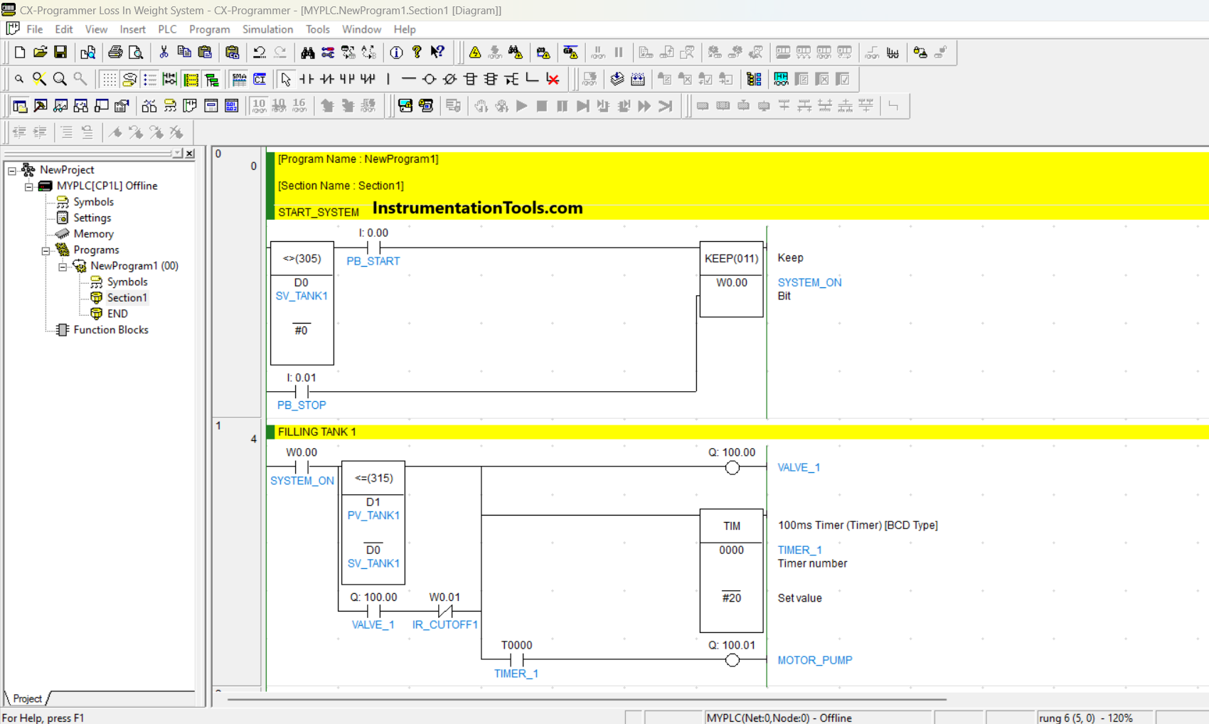
RUNG 2 (CUTOFF TANK1)
In this Rung, when the NO contact of memory bit SYSTEM_ON (W0.00) is in a HIGH state and the value in memory word PV_TANK1 (D1) equals “100”, then the Output memory bit IR_CUTOFF1 (W0.01) will be in a HIGH state.
RUNG 3 (FILLING TANK2)
When the NO contact of memory bit SYSTEM_ON (W0.00) is in a HIGH state and the START_FILL (0.02) button is pressed, the Output VALVE_2 (100.02) will OPEN. If the value of memory word PV_TANK2 (D11) is equal to SV_TANK2 (D10), then the Output memory bit IR_CUTOFF2 (W0.02) will be in HIGH state and the Output VALVE_2 (100.02) will be CLOSED due to Interlock.
RUNG 4 (DRAIN)
When the NO contacts of memory bits SYSTEM_ON (W0.00) and IR_CUTOFF2 (W0.02) are in the HIGH state, then memory bit IR_VALVE3 (W0.03) will also be in a HIGH state. Because it uses the KEEP(011) instruction, memory bit IR_VALVE3 (W0.03) will remain in a HIGH state even though the NO contacts of memory bits SYSTEM_ON (W0.00) and IR_CUTOFF2 (W0.02) are in the LOW state.
Memory bit IR_VALVE3 (W0.03) will be in the LOW state if the value of memory word PV_TANK2 (D11) is zero “0”.
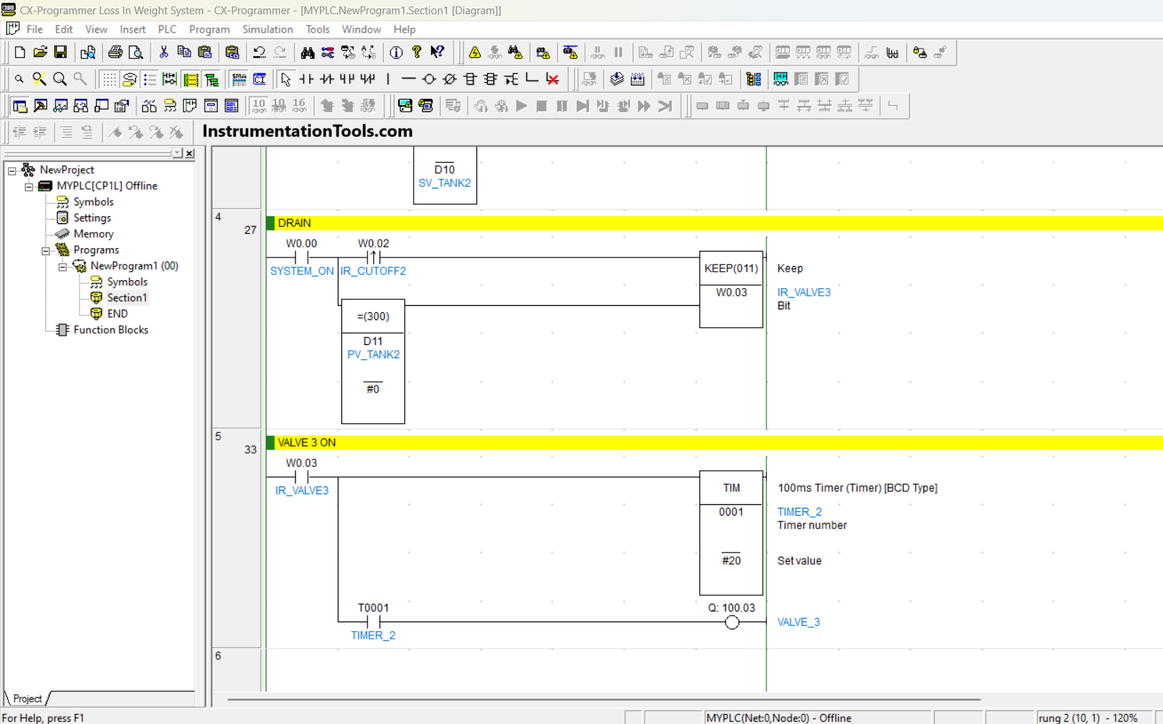
RUNG 5 (VALVE 3 ON)
When the NO contact of memory bit IR_VALVE3 (W0.03) is in the HIGH state, Timer TIMER_2 (T0001) will Start counting for 2 seconds. Once Timer TIMER_2 (T0001) finishes counting, Output VALVE_3 (100.03) will turn ON.
Output VALVE_3 (100.03) will turn OFF if the NO contact of memory bit IR_VALVE3 (W0.03) in LOW state.
Read Next:
- Medium-Level PLC Exercise for Students
- Basic PLC Exercise on Heater and Cooler
- PLC Program for Sequential Motor Control
- Schneider PLC Logic for Star-Delta System
- Schneider PLC Manual Sequential Machine