Inst ToolsInst ToolsInst Tools
  • Courses
  • Automation
    • PLC
    • Control System
    • Safety System
    • Communication
    • Fire & Gas System
  • Instrumentation
    • Design
    • Pressure
    • Temperature
    • Flow
    • Level
    • Vibration
    • Analyzer
    • Control Valve
    • Switch
    • Calibration
    • Erection & Commissioning
  • Interview
    • Instrumentation
    • Electrical
    • Electronics
    • Practical
  • Q&A
    • Instrumentation
    • Control System
    • Electrical
    • Electronics
    • Analog Electronics
    • Digital Electronics
    • Power Electronics
    • Microprocessor
Search
  • Books
  • Software
  • Projects
  • Process
  • Tools
  • Basics
  • Formula
  • Power Plant
  • Root Cause Analysis
  • Electrical Basics
  • Animation
  • Standards
  • 4-20 mA Course
  • Siemens PLC Course
Reading: Block diagram Algebra Objective Questions
Share
Notification Show More
Font ResizerAa
Inst ToolsInst Tools
Font ResizerAa
  • Courses
  • Design
  • PLC
  • Interview
  • Control System
Search
  • Courses
  • Automation
    • PLC
    • Control System
    • Safety System
    • Communication
    • Fire & Gas System
  • Instrumentation
    • Design
    • Pressure
    • Temperature
    • Flow
    • Level
    • Vibration
    • Analyzer
    • Control Valve
    • Switch
    • Calibration
    • Erection & Commissioning
  • Interview
    • Instrumentation
    • Electrical
    • Electronics
    • Practical
  • Q&A
    • Instrumentation
    • Control System
    • Electrical
    • Electronics
    • Analog Electronics
    • Digital Electronics
    • Power Electronics
    • Microprocessor
Follow US
All rights reserved. Reproduction in whole or in part without written permission is prohibited.
Inst Tools > Blog > Multiple Choice Questions > Block diagram Algebra Objective Questions

Block diagram Algebra Objective Questions

Last updated: November 27, 2021 5:41 pm
Editorial Staff
Multiple Choice Questions
No Comments
Share
4 Min Read
SHARE

Block diagram Algebra Objective Questions

1. Consider the block diagram shown below:

If the transfer function of the system is given by T(s)=G1G2+G2G3/1+X. Then X is:

a) G2G3G4
b) G2G4
c) G1G2G4
d) G3G4

Answer: b

Explanation: Use the technique of making two different block diagram by dividing two summers and use the approaches of shifting take off point and blocks.

2. For the block diagram given in the following figure, the expression of C/R is:
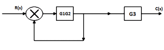
a) G1G2G3/1-G2G1
b) G1G2/1-G1G2G3
c) G1G2G3/1-G1G2G3
d) G1G2/G3(1-G1G2)

Answer: a

Explanation: Block diagram is being converted into signal flow graphs by considering each take off point as a node and each forward transfer function as forward gain.

3. The transfer function from D(s) to Y(s) is :
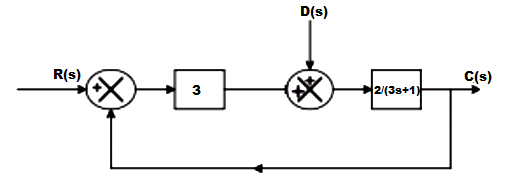
a) 2/3s+7
b) 2/3s+1
c) 6/3s+7
d) 2/3s+6

Answer: a

Explanation: Y(s)/D(s)=2/3s+1/1+3*(2/3s+1)=2/3s+7.

4. The closed loop gain of the system shown in the given figure is :
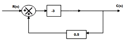
a) -9/5
b) -6/5
c) 6/5
d) 9/5

Answer: b

Explanation: C(s)/R(s)=-3/1+3/2=-6/5.

5. The advantage of block diagram representation is that it is possible to evaluate the contribution of each component to the overall performance of the system.

a) True
b) False

Answer: a

Explanation: The advantage of the block diagram is that it is possible to get the contribution of each block to the overall performance of the system.

6. The overall transfer function from block diagram reduction for cascaded blocks is :

a) Sum of individual gain
b) Product of individual gain
c) Difference of individual gain
d) Division of individual gain

Answer: b

Explanation: Gain of block get multiplied when they are cascaded where cascaded means that the blocks are in series combination with no summer in between.

7. The overall transfer function of two blocks in parallel are :

a) Sum of individual gain
b) Product of individual gain
c) Difference of individual gain
d) Division of individual gain

Answer: a

Explanation: The gains get added as the blocks are connected in parallel with the summer in between and they are connected with the same sign.

8. Transfer function of the system is defined as the ratio of Laplace output to Laplace input considering initial conditions________

a) 1
b) 2
c) 0
d) infinite

Answer: c

Explanation: By definition transfer function is the ratio of the laplace output to the input but the initial conditions mainly the stored energy is zero.

9. In the following block diagram, G1=10/s G2=10/s+1 H1=s+3, H2=1. The overall transfer function is given by :

a) 10/11s2+31s+10
b) 100/11s2+31s+100
c) 100/11s2+31s+10
d) 100/11s2+31s

Answer: b

Explanation: C/R=G2G1/1+G2H2+G1G2H2
C/R=100/11s2+31s+100.

10. Oscillations in output response is due to :

a) Positive feedback
b) Negative feedback
c) No feedback
d) None of the mentioned

Answer: a

Explanation: Oscillations are the unwanted sinuoidal signals with high gain in positive feedback and s the damping factor is absent in the positive feedback system entirely oscillations are present.

Don't Miss Our Updates
Be the first to get exclusive content straight to your email.
We promise not to spam you. You can unsubscribe at any time.
Invalid email address
You've successfully subscribed !

Continue Reading

Chromatographic Behaviour of Solutes Questions & Answers
The State Regulator Problem
Nitrogen Oxides Questions & Answers
Assessment of Relative Stability Using Nyquist Criterion
Encoder Multiple Choice Questions
Stepper Motors Objective Questions & Answers
Share This Article
Facebook Whatsapp Whatsapp LinkedIn Copy Link
Share
Leave a Comment

Leave a Reply Cancel reply

Your email address will not be published. Required fields are marked *

Stay Connected

128.3kFollowersLike
69.1kFollowersFollow
208kSubscribersSubscribe
38kFollowersFollow

Categories

Explore More

Effect of Adding a Zero to a System
Gas Chromatography Questions & Answers
Top 10 Industrial safety Objective Questions
Time Domain Analysis
Observer Systems
Standard Test Signals Objective Questions
NO2 Analyzer Questions & Answers
Amino-Acid Analyzers Questions & Answers

Keep Learning

Nonlinear Control Systems

Constructing Phase-Trajectories

Top 100 Power Plant Engineering Objective Questions & Answers

Top 100 Power Plant Engineering Objective Questions & Answers

Time Response Analysis

Time Response of First Order Systems Objective Questions

Time Response Analysis

State Variable Analysis – Part II

Ion Spectrometers Questions & Answers

Electron Spectroscopy for Chemical Analysis

Absorption Instrumentation Questions & Answers

Absorption Instrumentation Questions & Answers

Control Systems Stability and Algebraic Criteria

Necessary Conditions for Stability & Non-Linear Systems

Level Measurement Objective Questions

Level and Density Measurement Objective Questions

Learn More

Why we use -24vdc in vibration measurement

Why we use Negative Voltage in Vibration Measurement ?

Schottky Diode Vs PN junction Diode

Difference between Schottky Diode and PN junction Diode

absorption-type optical analyzer

Absorption Type Optical Analyzer

Losses of Transformer

Selecting the Proper Failure Mode

How to Select Control Valve Failure Mode

Difference Between PNP and NPN Sensors

Difference Between PNP and NPN Sensors

Lithium-ion Battery Charging System

Lithium-ion Battery Charging Systems

Peak Inverse Voltage of Center Tap Rectifier

Peak Inverse Voltage of Center Tap Rectifier

Follow US
All rights reserved. Reproduction in whole or in part without written permission is prohibited.
Welcome Back!

Sign in to your account

Username or Email Address
Password

Lost your password?