Inst ToolsInst ToolsInst Tools
  • Courses
  • Videos
  • Q & A
    • Interview
      • Instrumentation
      • Electronics
      • Electrical
      • Practical Questions
    • MCQ
      • Instrumentation MCQ
      • Electrical MCQ
      • Electronics MCQ
      • Control Systems MCQ
      • Analog Electronics MCQ
      • Digital Electronics MCQ
      • Power Electronics MCQ
      • Microprocessor MCQ
      • Multiple Choice Questions
  • EE
    • Electronics
      • Electronics Q & A
      • Electronic Basics
      • Electronic Devices & Circuits
      • Electronics Animation
      • Digital Electronics
    • Electrical
      • Electrical Basics
      • Electrical Q & A
      • Power Electronics
      • Electrical Machines
      • Electrical Animation
      • Power Systems
      • Switchgear & Protection
      • Transmission & Distribution
  • Measure
    • Control Valves
    • Calibration
    • Temperature
    • Pressure
    • Flow
    • Level
    • Analyzers
    • Switches
    • Vibration
    • Solenoid Valve
  • Control
    • PLC Tutorials
    • Control Systems
    • Safety Instrumented System (SIS)
    • Communication
    • Fire & Gas System
  • More
    • Design
    • Tools
    • Animation
    • Basics
    • Formulas
    • Standards
    • TextBooks
    • Common
    • Software
    • Excel Tools
    • Erection & Commissioning
    • Process Fundamentals
    • Videos
    • Books
Search
All rights reserved. Reproduction in whole or in part without written permission is prohibited.
Reading: Timer in Studio 5000 – TON, TOF, RTO
Share
Notification Show More
Font ResizerAa
Inst ToolsInst Tools
Font ResizerAa
  • Courses
  • PLC Tutorials
  • Control Systems
Search
  • Courses
  • Videos
  • Q & A
    • Interview
    • MCQ
  • EE
    • Electronics
    • Electrical
  • Measure
    • Control Valves
    • Calibration
    • Temperature
    • Pressure
    • Flow
    • Level
    • Analyzers
    • Switches
    • Vibration
    • Solenoid Valve
  • Control
    • PLC Tutorials
    • Control Systems
    • Safety Instrumented System (SIS)
    • Communication
    • Fire & Gas System
  • More
    • Design
    • Tools
    • Animation
    • Basics
    • Formulas
    • Standards
    • TextBooks
    • Common
    • Software
    • Excel Tools
    • Erection & Commissioning
    • Process Fundamentals
    • Videos
    • Books
Follow US
All rights reserved. Reproduction in whole or in part without written permission is prohibited.
Inst Tools > Blog > PLC Tutorials > Timer in Studio 5000 – TON, TOF, RTO

Timer in Studio 5000 – TON, TOF, RTO

One of the most common instructions used in PLC logic is a timer. The basic types of timers in Studio 5000 are TON, TOF, and RTO.

Last updated: May 7, 2024 1:50 pm
Viral Nagda
PLC Tutorials
No Comments
Share
6 Min Read
SHARE

One of the most common instructions used in PLC logic is a timer. Timers are required for almost all the operations. This is because controlled operations always require a delay for operation. Most of the applications have this requirement.

Contents
Timer in Studio 5000Types of TimersTimer ON (TON)Timer OFF (TOF)Retentive Timer (RTO)

Rockwell Automation is a very famous brand in industrial automation, and in that, the most used software is Studio 5000. They too have a very easy way of configuring timers. In this post, we will see the timer instructions in Studio 5000.

Timer in Studio 5000

A timer in Studio 5000 software has five pins – two for input and three for output. The input pins are Enable and Preset. Enable (En) is used to enable or disable the timer.

Preset (Pre) is used to define the setpoint of the timer. It works in milliseconds. So, if you want to run the timer for 5 seconds, then the setpoint will be entered as 5000 (as 5 seconds equals 5000 milliseconds).

The output pins are the Accumulator, Done bit, and Timing bit. The accumulator is the current timer value and runs in milliseconds. So, a current value of 2 seconds will show you as 2000 in the accumulator.

The done bit goes true when the timer operation is completed. The timing bit remains true as long as the timer is running. When the timer operation stops or pauses, then this bit too goes false.

You can enter the timer setpoint or show the timer current value in graphics through the DINT format of the variable. The value will be entered in milliseconds and you can either multiply it in the PLC program with 1000 or in the HMI expression with 1000.

Types of Timers

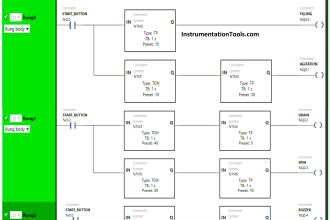
There are three basic types of timers in Studio 5000. They are

  • TON
  • TOF
  • RTO

Timer ON (TON)

The TON timer is an on-delay timer. Here, when the input goes true through the enable pin, then the timer starts to accumulate. During this time, the timing bit will also be ON.

Types of Timers in Studio 5000

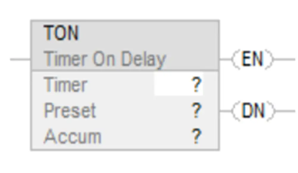
In between, if the timer condition goes false, then the accumulated value becomes zero and the timing bit too turns off. So, as long as the condition is true, the timer will accumulate.

Then finally, when the timer setpoint is reached, then the done bit goes true. The timer will again go to zero state if the condition goes false.

Timer OFF (TOF)

The TOF timer is an off-delay timer. Here, when the input goes true through the enable pin, then no action happens in any of the outputs.

Timer Off Delay TOF

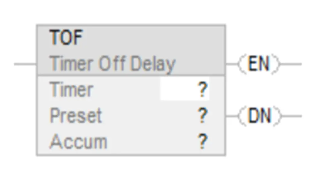
Now, if the timer condition goes false, then the timer starts to accumulate and the timing bit too turns on. So, as long as the condition is false, the timer will accumulate. In between, if the condition becomes true, then the timing bit goes false again and the accumulated value too becomes zero.

If the condition goes false and remains in that state, then the timer will again accumulate till the setpoint is reached. When it is reached, then the done bit goes true and the timing bit goes false. The cycle repeats after the condition goes true again.

Retentive Timer (RTO)

The RTO timer working is the same as the TON timer. The only difference is that if the timer is running and goes false in between, then the accumulated value will be held. Once the timer starts again, the timer will accumulate from the last held value.

Retentive Timer (RTO)

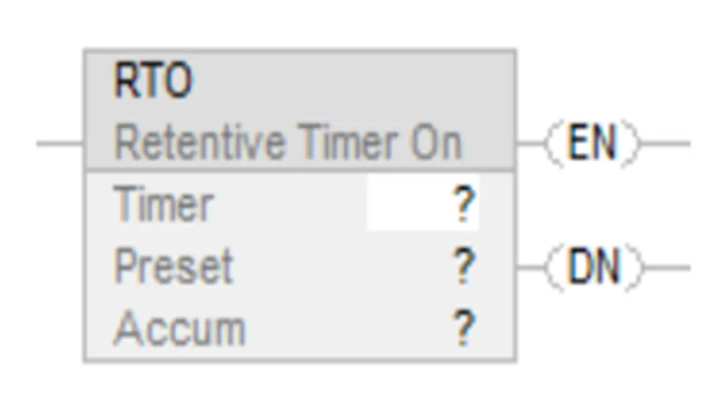
When the setpoint is reached, the done bit goes true. Now, one thing to note here is that if the condition goes false after this, then the done bit will remain on and the accumulated value too will be held. That means it has gone into a latched state.

To bring it back to zero state, an instruction called reset is used, where you have to turn it on by naming this timer instance in it. Then only the timer will reset.

If you liked this article, then please subscribe to our YouTube Channel for Instrumentation, Electrical, PLC, and SCADA video tutorials.

You can also follow us on Facebook and Twitter to receive daily updates.

Read Next:

  • Download Free CODESYS Software
  • Types of Instructions in PLC Programming
  • PLC Manufacturing Line Programming
  • Why is RTO used in the Place of TON Timer?
  • Programming and Tuning PID Controller in PLC
Don't Miss Our Updates
Be the first to get exclusive content straight to your email.
We promise not to spam you. You can unsubscribe at any time.
Invalid email address
You've successfully subscribed !

Recommended Articles

Industrial Networking and Wireless Interview Questions
PLC Counter Instructions
Pulse Generation using Timer in Siemens PLC
Parts of PLC
PLC Timer Instructions
Demo of a SCADA Software – Level Control System
Share This Article
Facebook Whatsapp Whatsapp LinkedIn Copy Link
Share
Leave a Comment

Leave a Reply Cancel reply

Your email address will not be published. Required fields are marked *

Stay Connected

128.3kFollowersLike
69.1kFollowersFollow
208kSubscribersSubscribe
38kFollowersFollow

Categories

Recent Comments

  • William Snyder on Top Non-PLC Certification Courses for Automation Professionals
  • Kamli on Top Free PLC Software
  • Guifty Shimica on Top Non-PLC Certification Courses for Automation Professionals
  • Guifty Shimica on Top Non-PLC Certification Courses for Automation Professionals

Related Articles

Structured Text PLC Program for Sequential Process Data Storage

Structured Text PLC Code for Sequential Process Data Storage

Save to Memory Card

How to Save a PLC Project to a Micro Memory Card?

SCADA

Top 100+ SCADA Questions

Control system architecture diagrams

Vendor Document for Project Systems Architecture

On Delay Timer using PLC

ON Delay Timer using PLC

DCS Vs PLC

Difference between DCS & PLC Systems

Pneumatic Circuit Design Using PLC - 2

PLC Pneumatic Circuit Control

PLC Program for Controlling Conveyors ON Sequence and OFF Sequence

PLC Program – Controls Conveyors ON and OFF Sequence

More Articles

Control Valve pressure recovery

What is Control Valve Flashing ?

Comparison between Transit time and Doppler Flow Meter

Difference between Transit time and Doppler Ultrasonic Flow Meter

Siemens PLC

Will PLCs become obsolete?

What is a Network Switch?

Network Switch Requirement in SCADA and DCS Architecture

Pyrometer

Pyrometers Handbook

How-to do Security of SCADA Systems

How-to do Security of SCADA Systems?

Faults in a Transformer

Batteries in parallel animation

Batteries in Series and Parallel Animation

Follow US
All rights reserved. Reproduction in whole or in part without written permission is prohibited.
Welcome Back!

Sign in to your account

Username or Email Address
Password

Lost your password?