Inst ToolsInst ToolsInst Tools
  • Courses
  • Videos
  • Q & A
    • Interview
      • Instrumentation
      • Electronics
      • Electrical
      • Practical Questions
    • MCQ
      • Instrumentation MCQ
      • Electrical MCQ
      • Electronics MCQ
      • Control Systems MCQ
      • Analog Electronics MCQ
      • Digital Electronics MCQ
      • Power Electronics MCQ
      • Microprocessor MCQ
      • Multiple Choice Questions
  • EE
    • Electronics
      • Electronics Q & A
      • Electronic Basics
      • Electronic Devices & Circuits
      • Electronics Animation
      • Digital Electronics
    • Electrical
      • Electrical Basics
      • Electrical Q & A
      • Power Electronics
      • Electrical Machines
      • Electrical Animation
      • Power Systems
      • Switchgear & Protection
      • Transmission & Distribution
  • Measure
    • Control Valves
    • Calibration
    • Temperature
    • Pressure
    • Flow
    • Level
    • Analyzers
    • Switches
    • Vibration
    • Solenoid Valve
  • Control
    • PLC Tutorials
    • Control Systems
    • Safety Instrumented System (SIS)
    • Communication
    • Fire & Gas System
  • More
    • Design
    • Tools
    • Animation
    • Basics
    • Formulas
    • Standards
    • TextBooks
    • Common
    • Software
    • Excel Tools
    • Erection & Commissioning
    • Process Fundamentals
    • Videos
    • Books
Search
All rights reserved. Reproduction in whole or in part without written permission is prohibited.
Reading: One-Shot Rising and Falling Edge Instructions in Rockwell PLC
Share
Notification Show More
Font ResizerAa
Inst ToolsInst Tools
Font ResizerAa
  • Courses
  • PLC Tutorials
  • Control Systems
Search
  • Courses
  • Videos
  • Q & A
    • Interview
    • MCQ
  • EE
    • Electronics
    • Electrical
  • Measure
    • Control Valves
    • Calibration
    • Temperature
    • Pressure
    • Flow
    • Level
    • Analyzers
    • Switches
    • Vibration
    • Solenoid Valve
  • Control
    • PLC Tutorials
    • Control Systems
    • Safety Instrumented System (SIS)
    • Communication
    • Fire & Gas System
  • More
    • Design
    • Tools
    • Animation
    • Basics
    • Formulas
    • Standards
    • TextBooks
    • Common
    • Software
    • Excel Tools
    • Erection & Commissioning
    • Process Fundamentals
    • Videos
    • Books
Follow US
All rights reserved. Reproduction in whole or in part without written permission is prohibited.
Inst Tools > Blog > PLC Tutorials > One-Shot Rising and Falling Edge Instructions in Rockwell PLC

One-Shot Rising and Falling Edge Instructions in Rockwell PLC

Learn the functions and working principle of one-shot rising edge and one-shot falling edge instructions in Rockwell PLC.

Last updated: October 19, 2023 2:56 pm
Editorial Staff
PLC Tutorials
No Comments
Share
6 Min Read
SHARE

In any PLC, it is important to understand how its instructions have been written. The basic understanding is the same in all the languages; the difference is how it is illustrated. If we are clear with the instructions, then we can work with any type of PLC software.

Contents
One Shot Rising Edge (OSR)One Shot Falling Edge (OSF)

One of the most widely used brands in automation is Rockwell. There are many different types of instructions in it for programming. In that, there are two instructions that are mostly required in any PLC logic. They are – One-shot rising edge and one-shot falling edge. In this post, we will see the working of these two instructions.

One Shot Rising Edge (OSR)

In PLC programming, you must have heard two common types of objects – positive peak and negative peak. A positive peak means that it takes a trigger only when the variable changes from 0 to 1. The output of this object comes in a trigger pulse type.

Now, instead of the variable state, there is one additional instruction in PLCs where you get the trigger output of the whole rung. This means, that when the whole rung or condition changes its state from 0 to 1, then the output will come in a pulse-type trigger condition. This is rising trigger instruction in PLC. In Rockwell PLC, it is called one-shot rising edge instruction.

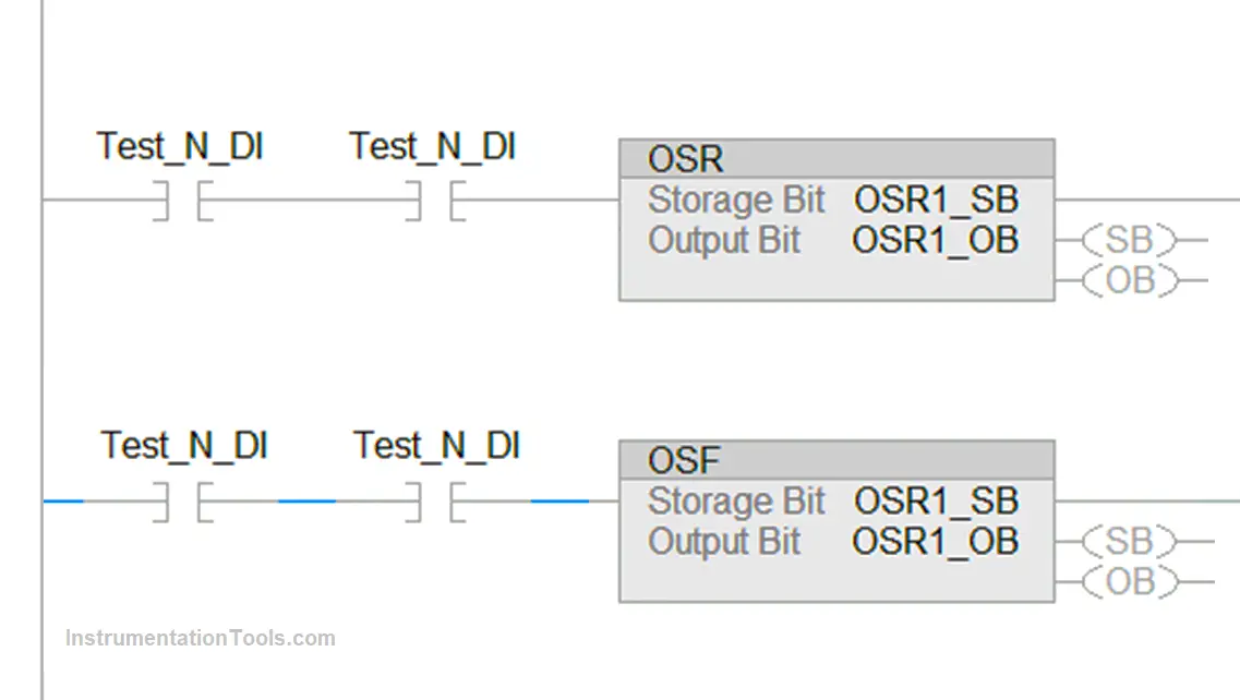
Refer to the below image for understanding. As you can see, the instruction takes two inputs in its condition. Both are written as NO logic; meaning when both are on, then only the condition is true. Now, when this happens, the instruction has two variables in it – storage bit and output bit. The function of the storage bit is to store the condition state.

When both the bits turn on and the condition changes from 0 to 1, then the storage bit gets updated as 1 and passes on this value to the output bit. The output bit turns on for a very short duration of time, in milliseconds. This pulse output can then be used by the PLC programmer in his logic.

As long as the condition is true, the storage bit does not change. As soon as the condition becomes false, the storage bit is updated with 0. When again the condition becomes true, then the output bit turns on as a pulse.

One-Shot Rising and Falling Edge Instructions in Rockwell PLC

This shows that this instruction is very useful when you want to turn an output by only a pulse, and this pulse must be generated only when the whole condition is true, and not when a single variable becomes true.

One Shot Falling Edge (OSF)

Now, take an example where it is required to take action when the system is stopped. This means, that when the condition becomes false from true, then some action must be taken. And the action must be done in a trigger type; it should not be continuously on. This is called a negative peak. To execute this function, either a negative peak must be taken from the variable or the negative peak must be taken from the whole condition as discussed earlier. For the second type, one-shot falling edge instruction is used in Rockwell PLC.

Refer to the above image. There are 2 NO conditions in the rung, and the output of this rung is connected to the OSF block. The block has two bits – storage and output. The storage bit is used to store the condition of the rung.

When the condition becomes true, then the storage bit is updated to 1. When the condition becomes false from true, then the storage bit is updated to 0 and the output bit becomes 1 in a pulse form. The cycle repeats again when the condition becomes true once again. The output bit is in pulse form and is on for a very short time, in milliseconds.

This shows that this instruction is very useful when you want to turn an output by only a pulse, and this pulse must be generated only when the whole condition is false, and not when a single variable becomes false.

In this way, we saw the one-shot rising edge and one-shot falling edge instructions in Rockwell PLC.

If you liked this article, then please subscribe to our YouTube Channel for Electrical, Electronics, Instrumentation, PLC, and SCADA video tutorials.

You can also follow us on Facebook and Twitter to receive daily updates.

Read Next:

  • AENT Module Rockwell PLC
  • Comparison of Control Loops
  • Top Best Practices of PLC Wiring
  • Site Commissioning Steps for PLC
  • Top 100 PLC Projects for Students
Don't Miss Our Updates
Be the first to get exclusive content straight to your email.
We promise not to spam you. You can unsubscribe at any time.
Invalid email address
You've successfully subscribed !

Continue Reading

What is Alarm Prioritization? – Types of Alarms
PLC Level Control of Two Tanks
PLC Program for Traffic Light Sequence using Functional Blocks
PLC Programming for Loss in Weight Liquid Systems
PLC Programming for Traffic Barrier Control
Structured Text PLC Code for Sequential Process Data Storage
Share This Article
Facebook Whatsapp Whatsapp LinkedIn Copy Link
Share
Leave a Comment

Leave a Reply Cancel reply

Your email address will not be published. Required fields are marked *

Stay Connected

128.3kFollowersLike
69.1kFollowersFollow
208kSubscribersSubscribe
38kFollowersFollow

Categories

Explore More

How to Configure IP Address in Rockwell PLC?
What is a GSD File and Why it is required?
What is a Control Panel and its types?
PID in Siemens TIA Portal
Why different PLC Programming Languages were Developed?
How to Configure PID in Siemens PLC?
How to Save a PLC Project to a Micro Memory Card?
SAVE and BR Memory Instructions in Siemens PLC Programming
Free Allen Bradley PLC Ladder Logic Training Course
Rules for Writing SCL Language in Tia Portal

Keep Learning

Classification of Fuses

Step-by-Step Guide to Choose Right Fuse for a Panel

Data Types in PLC

Data Types in PLC – Bit, Byte, Integer, Real, String

Siemens TIA Portal Free Version Download

Siemens TIA Portal Free Version Download

Why Use Normally-Closed Contact for Stop Buttons

Why Use Normally-Closed Contact for Stop Buttons?

PLC Logic to identify empty bottles in Packing

Automatic Empty Bottle detection using PLC Logic

Falling Positive and Falling Negative Instructions in PLC

Positive and Negative Edges using Statement List Language

DCS Marshalling Cabinet Checks

PLC, DCS, and ESD Marshalling Cabinet Checks

Programmable Logic Controller Boiler Logic

PLC Ladder Logic for Start-up Control of Boilers

Discover More

Gas Analyzers Interview Questions

Gas Analyzers Interview Questions and Answers

Nano Instrumentation Objective Questions

Nano Instrumentation Objective Questions

Electrical Machines Questions and Answers

Transformer as a Magnetically Coupled Circuit

How to Run Multiple Motors with a Single VFD

How to Run Multiple Motors with a Single VFD?

Digital Readout Systems Objective Questions

Digital Readout Systems Objective Questions

Sensors and Transducers Test

Sensors and Transducers Test

Transducer

What is a Transducer ?

Magnatic Level Indicators Working Animation

Magnetic Level Indicators Working Animation

Follow US
All rights reserved. Reproduction in whole or in part without written permission is prohibited.
Welcome Back!

Sign in to your account

Username or Email Address
Password

Lost your password?