In this article, we will learn about the boiler feed water circulation system, natural, forced, combined circulation, and blowdown water.
Boiler Feed Water Circulation System
- Boiler-feed water in power plants plays a crucial role in steam generation.
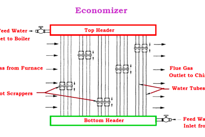
- Generally, water tubes are connected between the boiler drum at the top and the tube header at the bottom in the case of a water tube boiler
- This feed water circulates within the tube, boiler drum, and header.
- The rate of steam generation is in proportion to the water circulation rate.
- The circulation rate must be adequate to remove the heat from tube surfaces.
- A slow circulation of water may cause the formation of large bubbles and hence the possibility of tube burning.
- This feed water circulation must be unidirectional which means in one direction.
- There are two types of feed water circulation employed
- Natural circulation by the gravity force.
- Forced circulation by employing pumps. or
- A combination of both natural and force is generally employed.
Natural Circulation
A diagrammatic representation of the natural circulation of boiler feed water is shown below
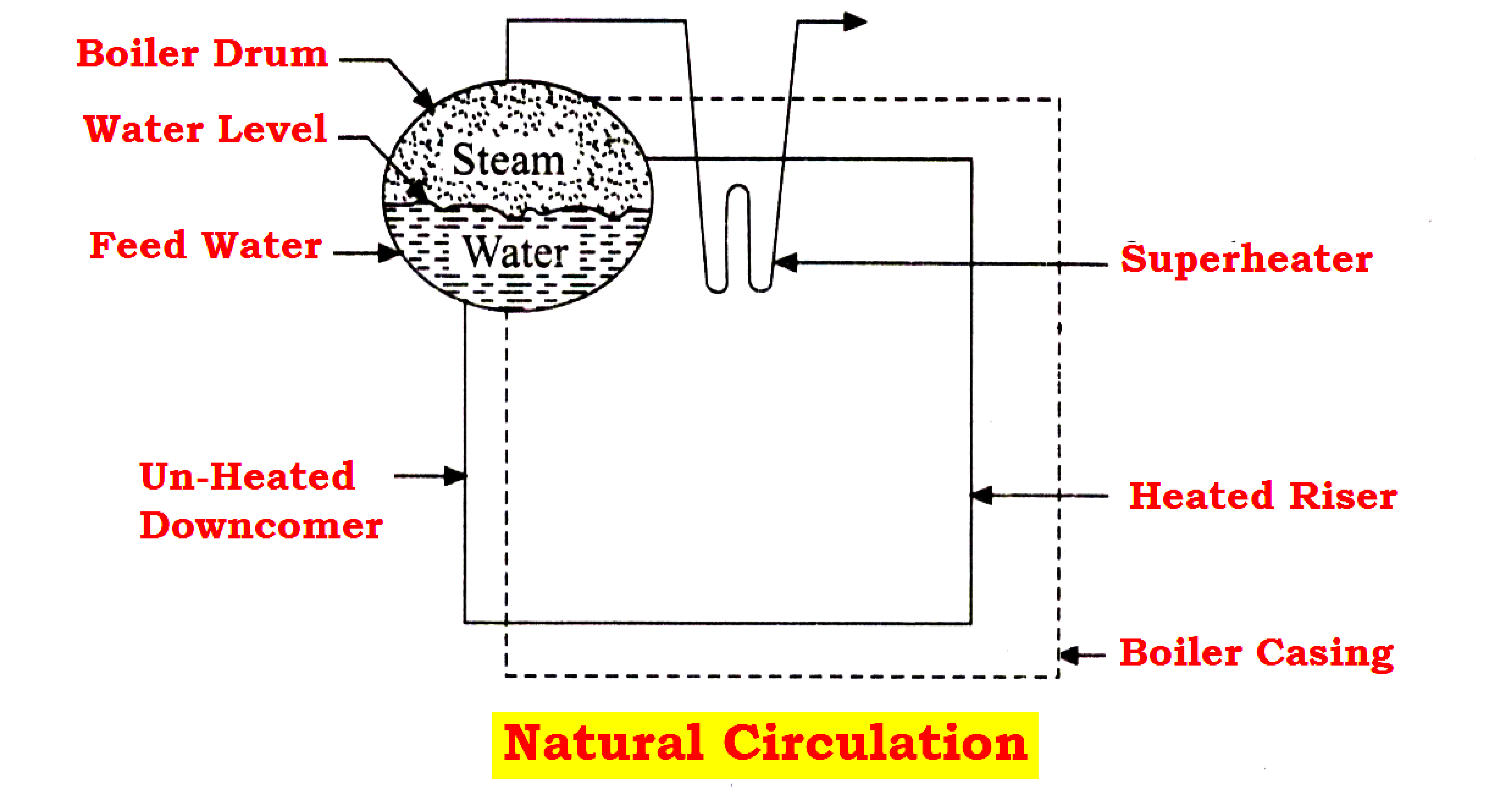
- Heating the riser tubes by using hot flue gasses coming out of the furnace causes the water circulation and steam to be released in the boiler drum.
- The density variation of feed water in the downcomer and the steam water mixture in the riser circuit makes the water circulation easy.
- The density of water and steam is low and the heat is absorbed in the raiser.
- The saturated steam with lower density is delivered to the boiler drum.
- The combination of low-density water in the downcomer develops the required force to establish circulation.
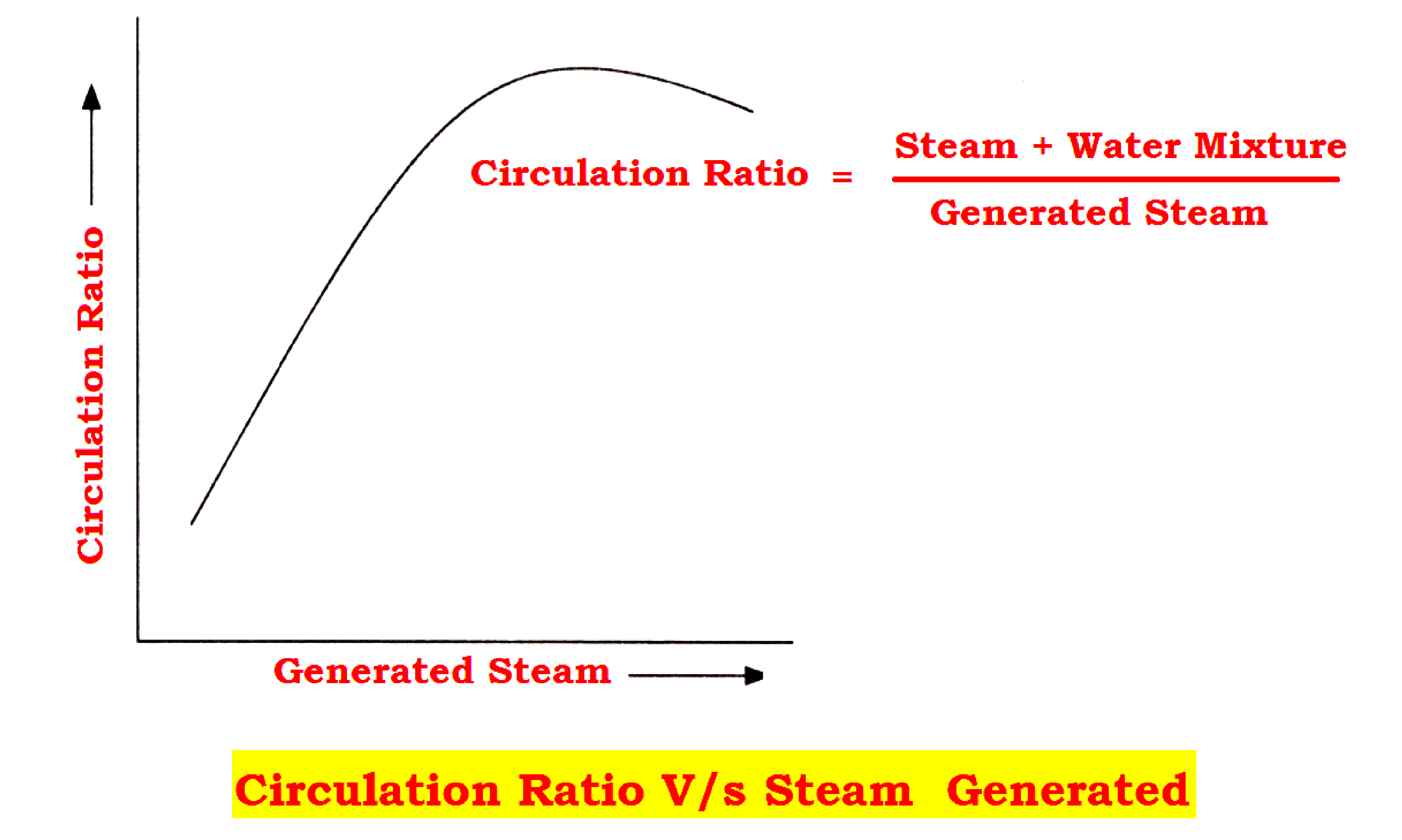
- The ratio between the mixture of water and steam flowing into the drum and the steam produced is known as the circulation ratio.
- With increased heat input, the steam output and circulation ratio increase to a certain limit.
- An increase in heat input reduces the flow rate.
- Hence it is required to design the water circuit such that the operation point must always lie in the region of the rising part of the curve.
Forced Circulation and Combined Circulation
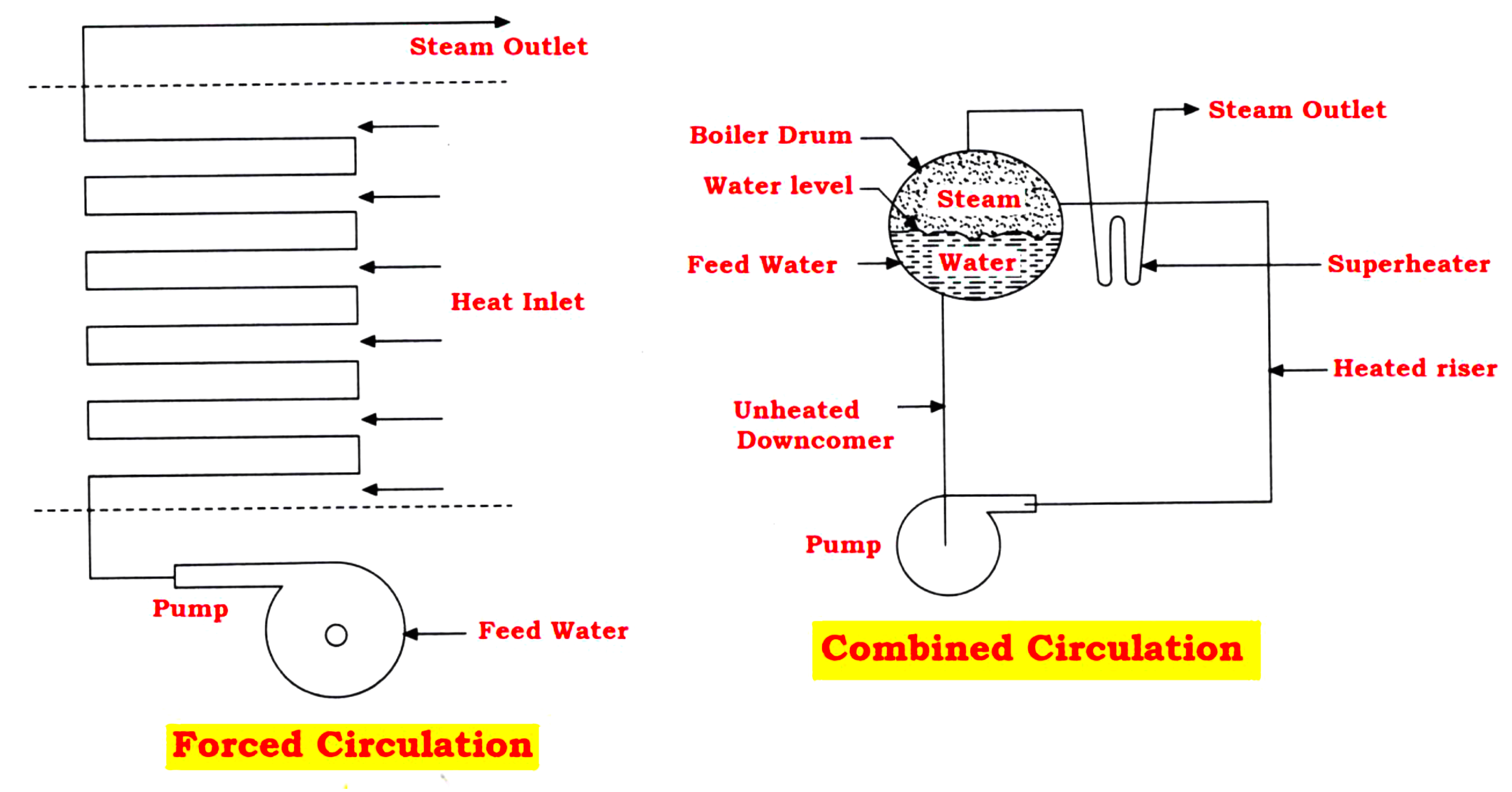
- Forced or positive circulation in boilers uses an external pump to force water or steam through the boiler circuits. One such system called once-through circulation is shown in the figure above
- This Combined Circulation involves both natural circulation by the force of gravity, and forced circulation using the external pump such a circulation system is shown in the figure above
Feed Water Supply
- The feed water plays a crucial role in power plants for steam production.
- Initially, This feed water is first converted into saturated steam in the combustion chamber area and finally converted to superheated steam in the superheater.
- After utilizing heat energy in the steam turbine to rotate the turbo alternator, the steam is now condensed in the condenser vessel and recirculated again as feed water.
- The physical condition of the feed water such as pressure, temperature, and quantity is measured at various locations.
- The chemical condition of the feed water is determined by measuring conductivity, pH, dissolved oxygen, etc.
- The determination of chemical conditions is more complex compared to the conclusion of physical conditions.
- But knowing the chemical condition is also very important for the safety and life of steam generators and turbines.
- But, It is difficult to get such pure water from natural sources.
- Even potable water supplied by local bodies like corporations and municipalities are not fit for continuous use as feed water.
Based on the source, location, and application of feed water in the boiler operation are known as:
Raw Water
- It is natural water along with impurities and minerals graced by the earth.
- Raw water is available as ‘Ground Water’ or as ‘Surface Water’.
Ground Water
The water is available from wells and springs with some hardness dissolved in it.
Surface Water
The water from river streams, ponds, and lakes have a dissolved hardness like groundwater and insoluble organic and inorganic matter.
- Since this surface water is turbid.
- Generally, natural water needs ‘softening’ for the removal of dissolved solids and ‘clarification’ for the removal of turbidity.
Boiler Feed Water
- The water is introduced into a boiler to replace the evaporation.
- This feed water must be pumped by the feed pump at higher pressure sufficiently above boiler drum pressure for correct flow into the boiler.
- The feed water is made to pass through an economizer to pick up some heat coming from waste flue gasses to increase the efficiency of boiler operation.
Blowdown
- Blowdown Water is the water drained from the boiler system.
- Depending on the blowdown connection point, the impurity content is higher or slightly equal to the boiler feed water
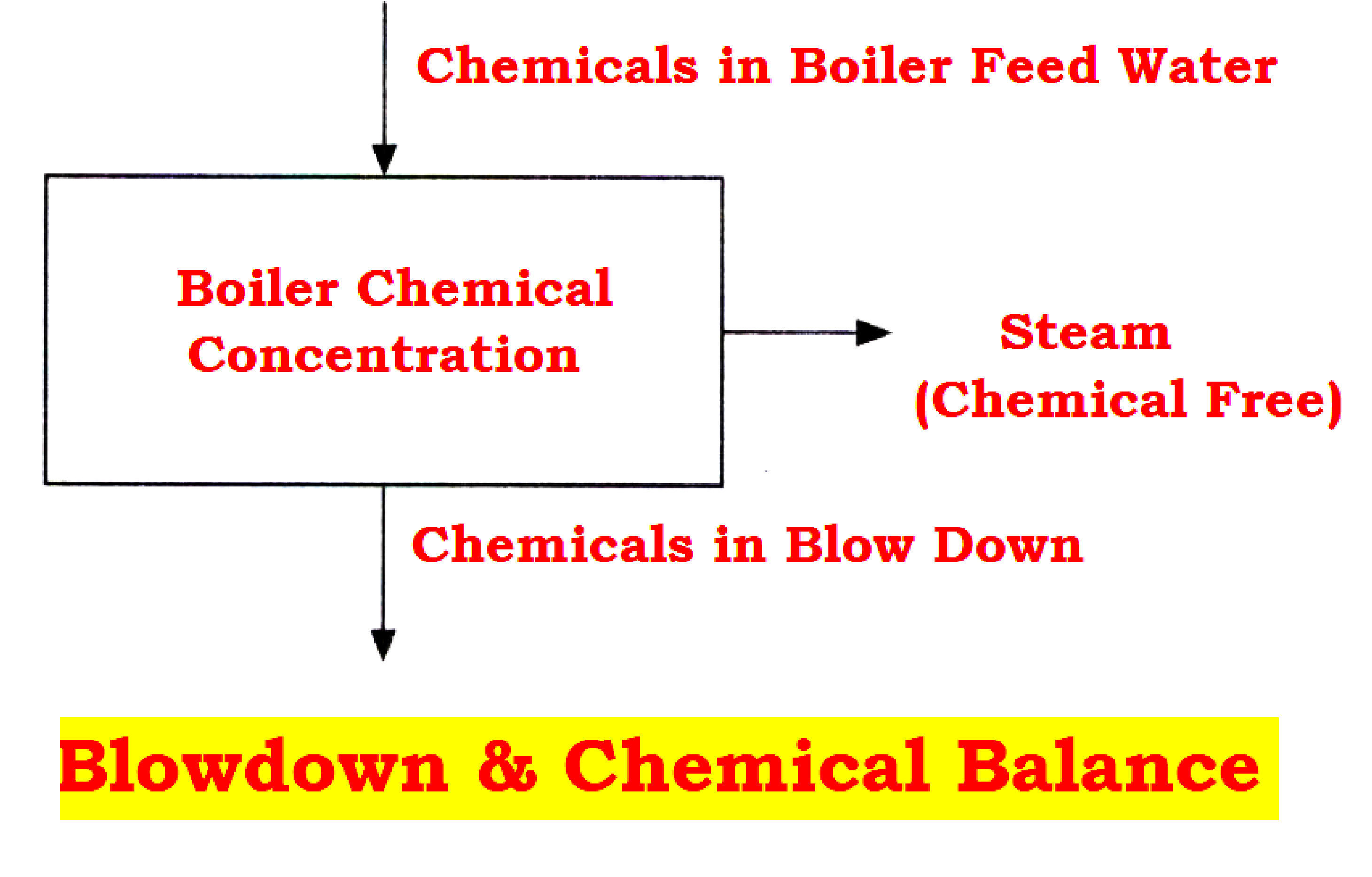
- A proper chemical balance in all boilers must be maintained.
- The boiler steam scrubbers are provided to prevent chemical content in the steam.
- All chemicals that have entered the boiler through the injection pump or in the feed water must ultimately be removed in the boiler blow-down.
- Assuming a constant level of chemical concentration in the boiler water and also in the feed water, the chemical concentration of the water in the boiler is determined by the ratio of blow-down flow to feed water flow.
- If the average blow-down flow is 10 percent of the feed water flow, then the chemical concentration of the boiler water is 10 times that of the feed water.
Blowdown Flow = Feed water Flow / Concentration Ratio
Condensate Water
- The steam generated from the boiler is used in the turbine for power generation.
- The exhaust steam coming from the steam turbine is condensed in the condenser vessel with the help of circulating cooling water and collected in the hot well.
- This condensate water collected in the hot well is reused as feed water and it does not require any treatment because of no impurities present in it.
Make-up Water
Boiler Feed Water = Condensate Water + Makeup Water
- The condensate water is not sufficient as feed water because some portion of feed water is lost in the process as loss of water in the boiler system including blow down and loss of water in the steam turbine system due to evaporation, leakages, etc.
- To make up for that, raw water has to be treated and added to the condensate water.
- In a continuous boiler operation, the treatment is only required for make-up water known as boiler feed water.
Cooling Water
- A huge quantity of cooling water is required to condense the steam and reduce the steam pressure in the condenser.
- This required cooling water is taken from the river or pond, but this water is not considered boiler-feed water because this water is not treated.
- The heat absorbed by this water can be removed by sending this water to the cooling tower then the same water can be re-circulated.
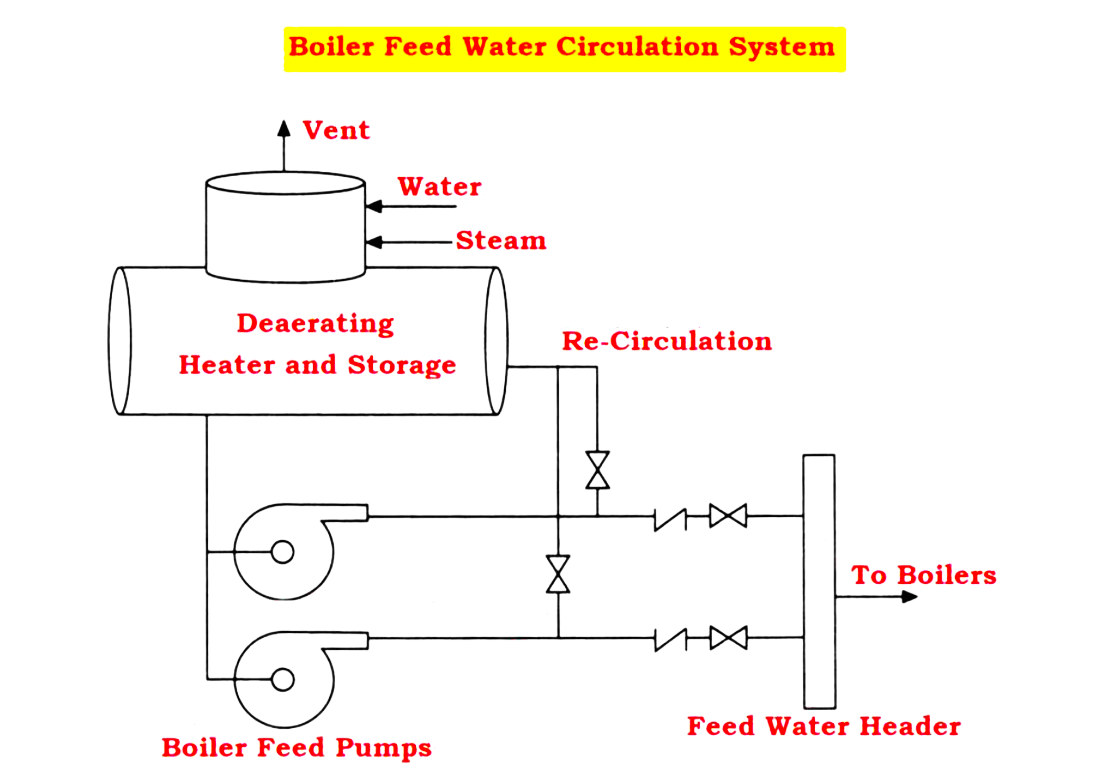
- A typical boiler feed water supply consists of two parts, makeup water treated in the water treatment plant and condensate water. The feed water is heated and pumped by feed water pumps to the boiler.
- This boiler feed water is pumped to the deaerating heater inside the deaerator to get heated with a help of steam. While heating helps to improve boiler efficiency, de-aeration helps to remove dissolved gasses like oxygen and carbon dioxide.
If you liked this article, then please subscribe to our YouTube Channel for Electrical, Electronics, Instrumentation, PLC, and SCADA video tutorials.
You can also follow us on Facebook and Twitter to receive daily updates.
Read Next:
- What are Oil Burners?
- Power Plant Blackout
- Boiler Safety Interlocks
- Deaerator Control System
- Turbine Speed Control system