It is very important to perform timely maintenance on Safety Instrumented System (SIS) for the safe, reliable operation of the plants.
SIS maintenance is also auditable by external certifying agencies on Safety systems (applicable as per the government regulations, varies in each country).
Brief of SIS Maintenance
As plant facilities having SIS goes into operation, Maintenance has three primary responsibilities:
- Perform SIS-related proof-testing.
- Define the frequency of SIS components to be proof-tested.
- Perform SIS repairs as needed.
- This is to ensure the time up to which a sensor in multiple configurations can be allowed to stay out of service. Normally this shouldn’t exceed twice the scheduled frequency, otherwise, higher-level management authorization is required.
- Always maintain documentation about the results of SIS test and repairs
- The results of all tests and services performed on the SIS should be documented. This should note whether the service was planned or unplanned (including plant trip).
Rules for SIS Maintenance
SIS proof test intervals shall be established based upon Safety Integrity Level (SIL) and SIS configuration (hardware and software).
Proof test intervals are to be calculated using relevant tools for SIS and ensure it meets the safety requirement.
Periodic proof test documentation shall be kept for at least the last 2 tests to ensure the SIS integrity, if tests aren’t confirming the SIS requirement additional testing is to be planned.
Responsibilities
The responsibility of the plant maintenance team is to do proper maintenance of SIS in order to ensure that the required SIL of each safety instrumented function is maintained and to confirm the designed functional safety is maintained for the plant.
Maintenance – Proof Testing Requirements
The SIS shall be designed in accordance with the maintenance and testing requirements. A proof test is a physical test to determine if there are problems with an SIS or BPCS IPL component that the online diagnostics does not check.
For example, for a sensor, this could be plugging in the sensor line, a pinhole in the diaphragm, or undetected electronic drift. The proof test brings out faults/problems on the instrument if any.
Depending on redundancy and application, the proof test may require instruments to be pulled out of service or process units to be shut down. This is why it is very important to consider proof testing when designing an SIS.
In all cases, the goal of proof testing is to return the component to “as good as new”, so that the healthiness of the instrument is ensured.
Documenting Proof Test
The plant shall maintain records that certify that proof tests and inspections were completed as required.
These records shall include the following information as a minimum:
- Type, details of tests and inspections performed
- The date on which the tests and inspections have taken up
- Maintenance person name who performed the tests and inspections
- Instrument/Valves serial number or other unique identifier, e.g. loop number, tag number, equipment number, and SIF number
- The results of the tests and inspection and values, e.g. “as-found” and “as-left” conditions
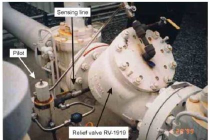
SIS Valves Leak Test Requirements
The performance of all SIS components must be periodically proven via proof testing including SIS category valves.
The degree to which an SIS valve is leak tested is determined by its required functionality. Based on the plant/ unit criticality some valves may require zero leakage.
Those valves that are determined to require a “bubble tight” leak performance (also called tight shutoff) due to exceptionally low leak limits necessary to maintain risk mitigation need to demonstrate this level of performance. Options for bubble-tight testing are conducting bench testing in a valve shop or in-line testing.
In some cases, SIFs can accept large leak rates as per calculations while maintaining risk mitigation. The leak test for the final element in this application/ service may be a visual inspection and checking in the field for stem movement by an experienced instrument technician.
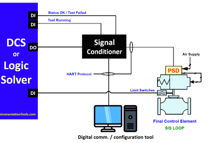
Logic Solver Testing
Proof testing, Repair, and Documentation procedures also apply to the logic solver.
The maintenance frequency of the logic solver may be different than the sensor & final control elements, usually the Proof testing of the logic solver is matched with the plant’s Turn Around or Major overhaul frequency so that the operations are not affected.
Even though the plant goes for shutdown the logic solver functionality may need to be retained to maintain some essential services viz. cooling water, Steam, etc.
The logic solver hardware must be periodically tested according to a written proof test procedure to detect unsafe/undiagnosed failures.