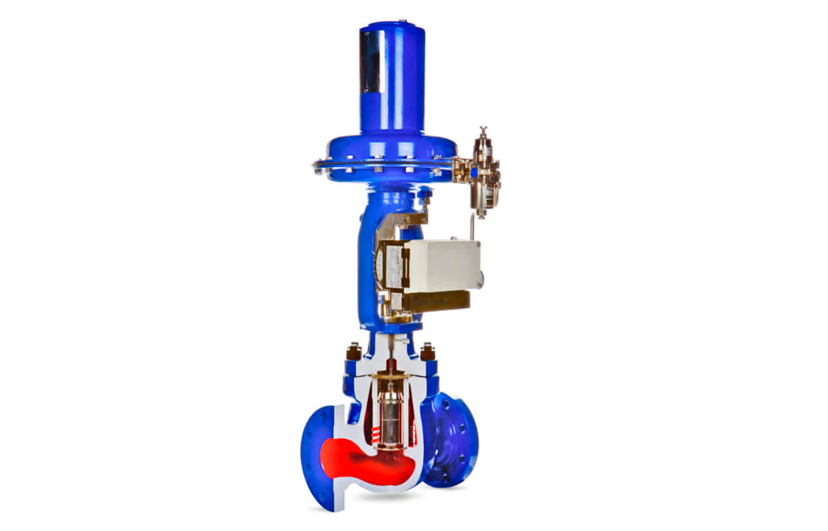
In this article, we will discuss the basic steps and procedure for the repair of Kent introl (KOSO) control valve.
Contents
Procedure for the Repair of Control Valve
The below steps mentioned the detailed step-by-step procedure for the repair of control valves.
- Close Upstream and downstream isolation valves of the control valve.
- Depressurize the line pressure by opening drain valves and flush with nitrogen.
- Remove all electrical and pneumatic connections to the control valve.
- Dismantle the control valve body, bonnet top flange along with actuator yoke.
- Inspect the valve internals and service the valve.
- Replace the damaged parts with OEM spares.
- Assemble the valve body and bonnet flange along with the actuator.
- Perform hydro test as per pressure rating of the control valve. (mentioned below)
- Normalize the electrical and pneumatic connections.
- Carry out smart valve positioner calibration and control valve stroke check.
- Close the drain valves.
- Normalize the upstream and downstream isolation valves.
Control Valve Hydro Test Procedure
Follow the below steps to carry out the hydro-test of a control valve.
- Remove the valve from the process line.
- Connect blinded flange in the control valve (c/v) outlet.
- Connect threaded flange in the c/v inlet.
- Connect Haskel pump set up in the inlet.
- Keep control valve at full open position.
- Using haskel pump, pressurize control valve body with water at 225Kg/cm2.
- Isolate the haskel pump set up and check for any leakages for 15 minutes.
- Depressurize the pressure in the valve body.
- Connect the valve back into process line.
Note:
- The haskel pump uses instrument air to operate and generates very high-pressure output. You can use any other available high-pressure pump for testing purposes.
- The specifications of control valves depends as per your installed base in your plant.
Credits: PLQP Instrumentation Team
If you liked this article, then please subscribe to our YouTube Channel for Instrumentation, Electrical, PLC, and SCADA video tutorials.
You can also follow us on Facebook and Twitter to receive daily updates.
Read Next: