Instrumentation engineering root cause analysis of stuck segment orifice dimensions calculations.
| Article Type: | Root Cause Analysis (RCA) |
| Category: | Instrumentation |
| Equipment Type: | Instruments |
| Author: | S. Raghava Chari |
Note: This root cause analysis (RCA) is from real-time scenarios that happened in industries during the tenure of two or three decades ago. These articles will help you to improve your troubleshooting skills and knowledge.
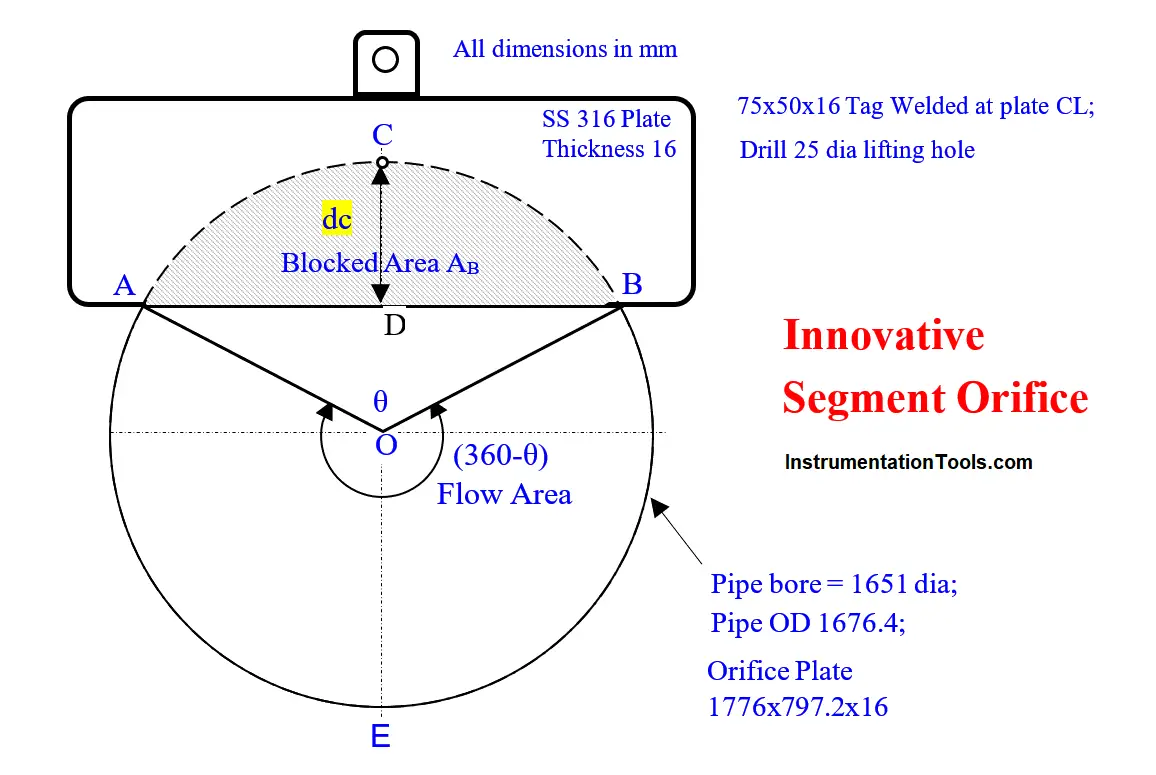
Segment Orifice Dimensions Calculations
Stuck Segment Orifice dimensions calculations might need Rs 20 million pump import.
Problem: Refer to Instrument problem discussed segment orifice plate (SOP).
| Segment Orifice Sizing | ||
| S.No. | Col A | Col B |
| 1. | Given m =0.57 the max orifice to pipe bore area for min pressure loss | 0.57 |
| 2. | Pipe bore area APB =PI()*500^2 | 785398 |
| 3. | Orifice Plate Opening area AO = 0.57*APB | 447677 |
| 4. | Arc ADB subtended Angle O (see fig) – | θ |
| 5. | Interior Angle AOB | (360- θ) |
| 6. | ▲AOB area =0.5*500^2*Sin(360- θ) | |
| 7. | Sector ADB area As = APB*θ/360 | |
| 8. | Flow opening area AFO =447677=(θAPB/360+0.5*R2Sin(360-θ)/2)) | |
| 9. | Put θ in an excel sheet cell and =(θAPB/360+0.5*R2Sin(360-θ)/2)) in another | |
| 10. | Key in different θ values to get closest to AFO of 447677 calculated in cell B3 | |
| 11. | Chord distance d=500*COS(RADIANS((360-B4)/2)) | 55.1 |
| 12. | In few key ins θ = 192.651O yields AFO=447676 – a surprisingly close value. And Chord distance =55.1 as above | |
| 13 | Mark the Chord 55.1 mm away from plate CL towards the tag, the arc ADB and cut Segment opening. Orifice is ready |
Calculating the chord distance from the plate CL was necessary to make the segment orifice plate.
The table shows where the engineer was stuck and how the author unstuck him.
Thanks to unsticking enabled chord distance, he calculated, the workshop cut the orifice plate opening and delivered the orifice plate for use.
Benefits
The plant realized the previous problem explained the innovation of just welding a plate in the pipe cut slot with the sharp edge 55 mm away from the pipe horizontal diameter line.
The plant realized all the Instrument Previous Problem discussed benefits
Author: S. Raghava Chari
Do you face any similar issues? Share with us through the below comments section.
If you liked this article, then please subscribe to our YouTube Channel for Instrumentation, Electrical, PLC, and SCADA video tutorials.
You can also follow us on Facebook and Twitter to receive daily updates.
Read Next:
- Pressure Switch Screwed Cover
- Too Low-Temperature Readings
- Pressure Switch Screwed Cover
- Thermowell Shank to Flange Leaks
- Magnetic Flow Meter Liner Damaged