Inst ToolsInst ToolsInst Tools
  • Courses
  • Videos
  • Q & A
    • Interview
      • Instrumentation
      • Electronics
      • Electrical
      • Practical Questions
    • MCQ
      • Instrumentation MCQ
      • Electrical MCQ
      • Electronics MCQ
      • Control Systems MCQ
      • Analog Electronics MCQ
      • Digital Electronics MCQ
      • Power Electronics MCQ
      • Microprocessor MCQ
      • Multiple Choice Questions
  • EE
    • Electronics
      • Electronics Q & A
      • Electronic Basics
      • Electronic Devices & Circuits
      • Electronics Animation
      • Digital Electronics
    • Electrical
      • Electrical Basics
      • Electrical Q & A
      • Power Electronics
      • Electrical Machines
      • Electrical Animation
      • Power Systems
      • Switchgear & Protection
      • Transmission & Distribution
  • Measure
    • Control Valves
    • Calibration
    • Temperature
    • Pressure
    • Flow
    • Level
    • Analyzers
    • Switches
    • Vibration
    • Solenoid Valve
  • Control
    • PLC Tutorials
    • Control Systems
    • Safety Instrumented System (SIS)
    • Communication
    • Fire & Gas System
  • More
    • Design
    • Tools
    • Animation
    • Basics
    • Formulas
    • Standards
    • TextBooks
    • Common
    • Software
    • Excel Tools
    • Erection & Commissioning
    • Process Fundamentals
    • Videos
    • Books
Search
All rights reserved. Reproduction in whole or in part without written permission is prohibited.
Reading: SFC Language in PLC Programming
Share
Notification Show More
Font ResizerAa
Inst ToolsInst Tools
Font ResizerAa
  • Courses
  • PLC Tutorials
  • Control Systems
Search
  • Courses
  • Videos
  • Q & A
    • Interview
    • MCQ
  • EE
    • Electronics
    • Electrical
  • Measure
    • Control Valves
    • Calibration
    • Temperature
    • Pressure
    • Flow
    • Level
    • Analyzers
    • Switches
    • Vibration
    • Solenoid Valve
  • Control
    • PLC Tutorials
    • Control Systems
    • Safety Instrumented System (SIS)
    • Communication
    • Fire & Gas System
  • More
    • Design
    • Tools
    • Animation
    • Basics
    • Formulas
    • Standards
    • TextBooks
    • Common
    • Software
    • Excel Tools
    • Erection & Commissioning
    • Process Fundamentals
    • Videos
    • Books
Follow US
All rights reserved. Reproduction in whole or in part without written permission is prohibited.
Inst Tools > Blog > PLC Tutorials > SFC Language in PLC Programming

SFC Language in PLC Programming

In this post, we will see the concept of SFC (Sequential Flow Chart) language in PLC programming with a basic example program.

Last updated: October 17, 2023 3:15 pm
Viral Nagda
PLC Tutorials
No Comments
Share
6 Min Read
SHARE

In this post, we will see the concept of SFC (Sequential Flow Chart) language in PLC programming with a basic example program.

Contents
Types of Languages in PLCSFC Language in PLCSequential Flow Chart ProgrammingSFC Programming Example

Types of Languages in PLC

The five types of languages used in PLC programming are as follows.

They are

  • Ladder (LD),
  • Structured text (ST),
  • Functional Block Diagram (FBD),
  • Sequential Flow Chart (SFC) and
  • Instruction List (IL).

SFC Language in PLC

A Sequential Flow Chart is a language used in PLC programming which is a graphical representation of the flowcharts or steps, which is similar to flowchart algorithms used in computer languages.

This language is a very useful tool in a condition where the process is very large and the functions are performed in steps.

Instead of writing the whole logic in a ladder diagram or even if you use functional block diagrams, the repetition rates and the overall viewing of the process can be made simpler by using SFC language.

Sequential Flow Chart Programming

Consider a simple example where you turn on or off a motor by pressing the start and stop buttons. Refer to the below image showing SFC language.

The black box represents action to be written inside the step. The brown line indicates the flow of the sequence.

The horizontal grey line in between indicates the transition condition.

SFC Language in PLC Programming

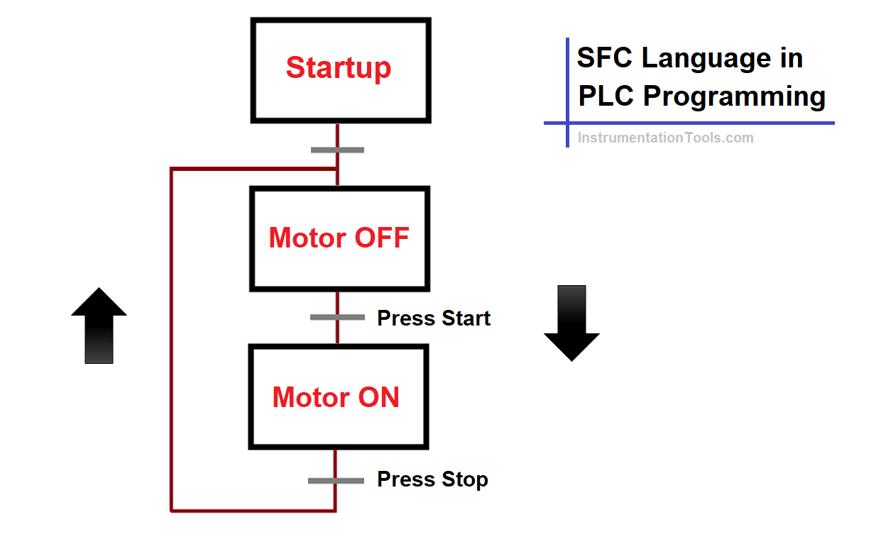
In the first box, a start-up condition of 2 seconds timer is written for starting this action. This step executes on PLC cold start or warm start.

This means that the start and stop action will be executed after an initial delay of 2 seconds of PLC start-up. The first transition condition is set to true. The second step is written to reset the motor variable.

The second transition condition is written for checking the start pushbutton press. The third step is written to set the motor variable. The third transition condition is written for checking stop pushbutton press.

So, the sequence will work as follows. On PLC start-up, after a delay of 2 seconds, the motor will be turned off by default in the second step as written.

Now, if the start button is pressed, the motor will be turned on as per the second transition condition and third step. If the stop button is pressed, the motor will be turned off as per the third transition condition and the second step.

This means that the logic will be executed as per the flow sequence lines written. A transition condition can be defined as an interlock for executing a step or action. You can write a variable or even call a section in a step.

SFC Programming Example

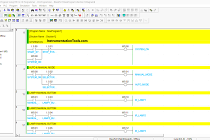
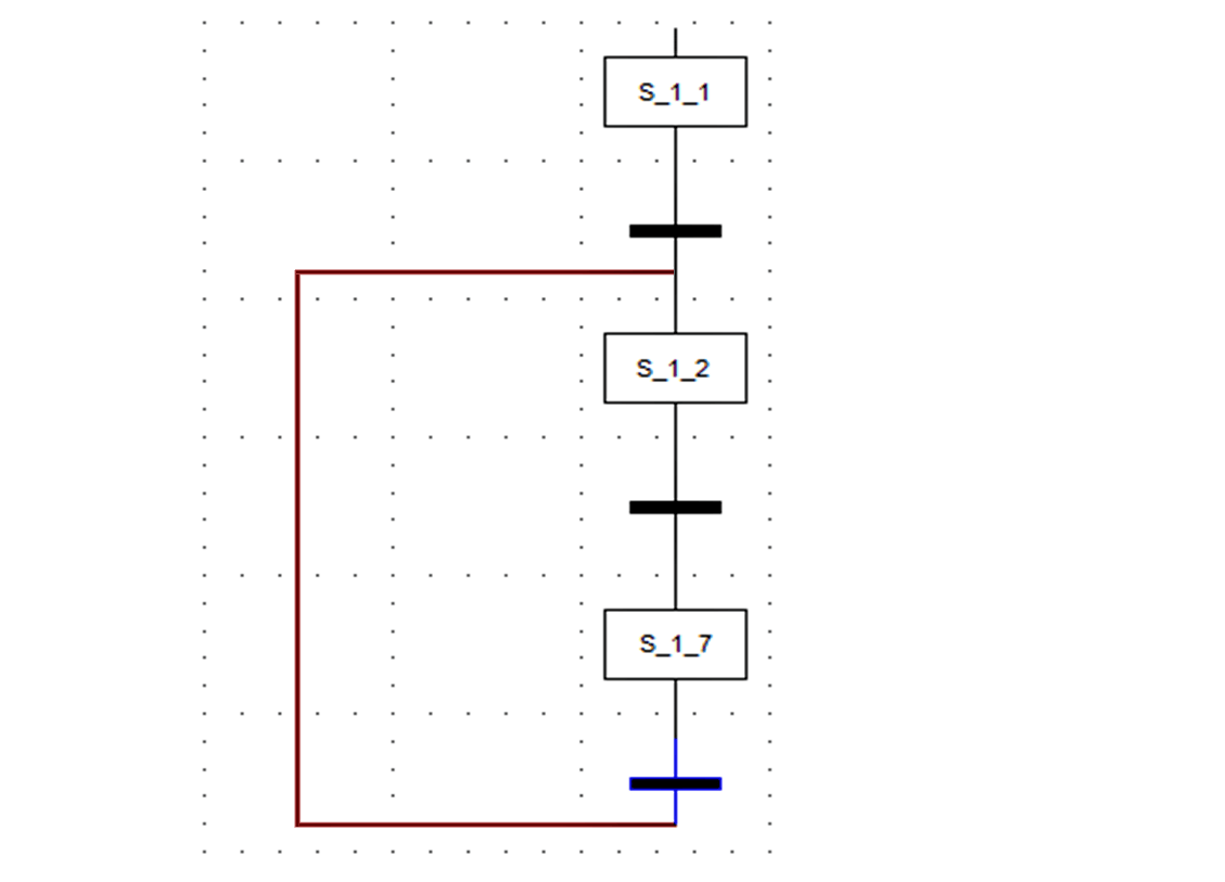
The below image is an actual example of the language written in PLC software.

In the box, you can define the action and in the black line, you can define the variable condition to be written.

Sequential Flow chart is a language used in PLC

SFC’s are useful in breaking a very complex flow chart sequence in a simpler way to execute the logic. You have to properly define the conditions and arrange the blocks and flow sequence accordingly to perform the function.

Remember to not get trapped in a repetitive or infinite loop which will not break the logic and can instead confuse the programmer in writing the logic.

You must have written this simple logic in a ladder language. But, it must be noted that you can also use SFC language for such logic or other complex ones.

Due to the visual representation of flowchart-type logic in front of the programmer, he can easily troubleshoot logic and also reduce the downtime required for developing a logic.

You can also use branching in the SFC language. That means, after a step, you can execute other parallel running steps like a branch.

In branching logic is a sub-category named selective branching. That means each branch will have its own individual transition condition to execute that branch/step.

Similar to branching, convergence is also possible. It is the opposite of branching. That means, all the branches combine together to execute a single step.

SFC’s are a strong tool in designing logic and making the sequence more understanding and easier to use.

If you liked this article, then please subscribe to our YouTube Channel for Instrumentation, Electrical, PLC, and SCADA video tutorials.

You can also follow us on Facebook and Twitter to receive daily updates.

Read Next:

  • Cybersecurity in PLC
  • Actuator Sensor Interface
  • Principle of Operation of PLC
  • Problem on PLC, HMI, VFD, and Motor
  • Virtual Reality in Industrial Automation
Don't Miss Our Updates
Be the first to get exclusive content straight to your email.
We promise not to spam you. You can unsubscribe at any time.
Invalid email address
You've successfully subscribed !

Continue Reading

STL Programming – SET, RESET, ASSIGN
How to Export Data from WinCC Runtime Advanced into Excel using VB Script
Modbus Communication between Delta PLC with VFD
Waste-Burning System OMRON PLC Program Example
200+ Quiz on Electrical Meters, Measurement, and Troubleshooting
PLC Ladder Logic Simulator Mobile Apps For Android
Share This Article
Facebook Whatsapp Whatsapp LinkedIn Copy Link
Share
Leave a Comment

Leave a Reply Cancel reply

Your email address will not be published. Required fields are marked *

Stay Connected

128.3kFollowersLike
69.1kFollowersFollow
208kSubscribersSubscribe
38kFollowersFollow

Categories

Explore More

PLC Mixing Logic in Liquids on EcoStruxure Machine Expert-Basic
3 to 8 Line Decoder PLC Ladder Diagram
PLC Functional Block Diagram for Logic Gates
PLC Ladder Logic for Tanks Filling as per Priority
Main differences between Sinking and Sourcing Circuits
PLC Analog I/O and Network I/O
What is CODESYS? Why Do You Need to Learn it?
Create Ladder Diagram from Boolean Logic

Keep Learning

User Defined Data Types - UDT

User Defined Data Types (UDT) – Purpose, Need, Tutorial

Learn about PLC, DCS, RTU, SCADA, and PAC

Learn about PLC, DCS, RTU, SCADA, and PAC

Types of Scan Time in a PLC

#16 PLC Best Practices – Create Trend for Cycle Time on HMI

Siemens PLC Interview Questions & Answers

Siemens PLC Interview Questions and Answers

Turbine-Compressor System Architecture

Turbine-Compressor System Architecture

Save to Memory Card

How to Save a PLC Project to a Micro Memory Card?

Difference Between Static and Temp Memory in Siemens TIA Portal

Difference Between Static and Temp Memory in Siemens PLC TIA Portal

Converter Instruction in Siemens PLC Programming

Converter Instruction in Siemens PLC Programming

Learn More

Analog Electronics Objective Questions

Analog Electronics Objective Questions – Set 3

P&ID Guidelines for Storage Tanks

P&ID Guidelines for Storage Tanks

igbt-symbol

Types of IGBT

Ultrasonic Level Measurement Questions and Answers

Ultrasonic Level Measurement Questions and Answers

Fire and Gas System Interview Questions & Answers

Fire and Gas System Interview Questions & Answers

Deaerator Pressure and Level Control System in Power Plants

Deaerator Pressure and Level Control System in Power Plants

Voltage Divider

Voltage Divider

feedforward control theory

Proportioning Feedforward action

Follow US
All rights reserved. Reproduction in whole or in part without written permission is prohibited.
Welcome Back!

Sign in to your account

Username or Email Address
Password

Lost your password?