Inst ToolsInst ToolsInst Tools
  • Courses
  • Automation
    • PLC
    • Control System
    • Safety System
    • Communication
    • Fire & Gas System
  • Instrumentation
    • Design
    • Pressure
    • Temperature
    • Flow
    • Level
    • Vibration
    • Analyzer
    • Control Valve
    • Switch
    • Calibration
    • Erection & Commissioning
  • Interview
    • Instrumentation
    • Electrical
    • Electronics
    • Practical
  • Q&A
    • Instrumentation
    • Control System
    • Electrical
    • Electronics
    • Analog Electronics
    • Digital Electronics
    • Power Electronics
    • Microprocessor
Search
  • Books
  • Software
  • Projects
  • Process
  • Tools
  • Basics
  • Formula
  • Power Plant
  • Root Cause Analysis
  • Electrical Basics
  • Animation
  • Standards
  • 4-20 mA Course
  • Siemens PLC Course
Reading: Contactor – Basics, Wiring, Connection with PLC
Share
Notification Show More
Font ResizerAa
Inst ToolsInst Tools
Font ResizerAa
  • Courses
  • Design
  • PLC
  • Interview
  • Control System
Search
  • Courses
  • Automation
    • PLC
    • Control System
    • Safety System
    • Communication
    • Fire & Gas System
  • Instrumentation
    • Design
    • Pressure
    • Temperature
    • Flow
    • Level
    • Vibration
    • Analyzer
    • Control Valve
    • Switch
    • Calibration
    • Erection & Commissioning
  • Interview
    • Instrumentation
    • Electrical
    • Electronics
    • Practical
  • Q&A
    • Instrumentation
    • Control System
    • Electrical
    • Electronics
    • Analog Electronics
    • Digital Electronics
    • Power Electronics
    • Microprocessor
Follow US
All rights reserved. Reproduction in whole or in part without written permission is prohibited.
Inst Tools > Blog > Electrical Basics > Contactor – Basics, Wiring, Connection with PLC

Contactor – Basics, Wiring, Connection with PLC

A contactor is a device that is used to control the supply of a three-phase power supply in an electrical circuit.

Last updated: October 17, 2023 3:46 pm
Viral Nagda
Electrical Basics PLC Tutorials
No Comments
Share
4 Min Read
SHARE

In this post, we will see the working of a contactor, wiring and terminals, and connection between the contactor and a PLC system.

Contents
Connection between PLC and ContactorWorking of ContactorRelay Versus ContactorContactor Terminals and Wiring

A contactor is a device that is used to control the supply of a three-phase power supply in an electrical circuit.

The contactor’s role is to switch on or off the power supply to its connected output load.

Connection between PLC and Contactor
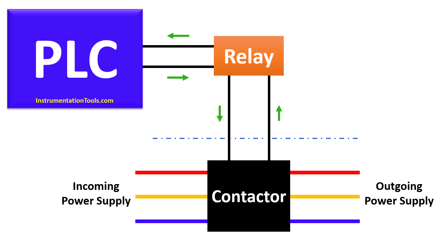
Contactor wiring to PLC System

As seen in the image above, the contactor has three connections – a three-phase power supply, a contact for energizing it, and a contact for giving feedback to the PLC.

The image shown describes the generally used setup for connecting a contactor to the PLC or relay.

Working of Contactor

Let us understand the working of a contactor. When the PLC digital output turns on, the relay is energized.

The output contact (NO) of the relay becomes closed and passes a supply potential connected through its common terminal to the NO contact and then to the contactor pin.

This energizes the contactor and switches on the three-phase supply connected at its input terminal to its output terminal. The contactor then passes its running feedback back to the PLC through an auxiliary contact connected to it.

Due to this setup, three-phase equipment (for example a motor) gets controlled by a PLC in a safe manner.

Video: PLC and Pump Control

Relay Versus Contactor

Many people ask whether they can directly connect a relay to the motor; as a relay too is a contact device. It should not be done, as the voltage and current ratings of a relay are very small as compared to a contactor. 

A relay cannot handle a large load like a motor and also, there are very few relay devices available in the market which has a three-phase connection in it.

Contactor Terminals and Wiring
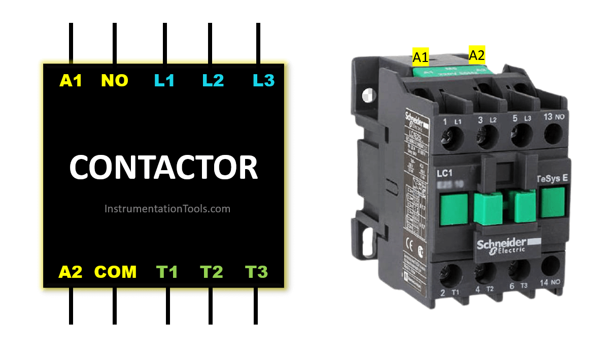
Contactor Terminals and Wiring

Refer to the above image to understand its wiring. A1 and A2 are energizing contacts.

There are DC and AC options available in it. NO/NC and COM are the auxiliary contacts that get energized depending on the switching of the contactor.

L1, L2, and L3 are the input three-phase terminals. T1, T2, and T3 are the output three-phase terminals. L1 is switched to T1, L2 is switched to T2, and L3 is switched to T3 when the contactor is turned ON.

In some circuits, an overload relay is connected after the connector. It monitors the overcurrent of the motor and trips the circuit in case of a short circuit or over current. Its use depends on the application.

This is the working of a contactor. Basically, it is used for switching purposes and to control heavy and high voltage devices.

If you liked this article, then please subscribe to our YouTube Channel for Instrumentation, Electrical, PLC, and SCADA video tutorials.

You can also follow us on Facebook and Twitter to receive daily updates.

Read Next:

  • Interposing Relay Panel
  • Intelligent Motor Control Center
  • Motors and Alternators Quiz
  • Mitsubishi PLC Training Course
  • What is a Safety Relay?
Don't Miss Our Updates
Be the first to get exclusive content straight to your email.
We promise not to spam you. You can unsubscribe at any time.
Invalid email address
You've successfully subscribed !

Continue Reading

PLC Problems Troubleshooting
VFD Interview Questions and Answers – Electrical Drives
All About Electric Fence Gates
Top Automation Vendors from Around the World – An Overview
Transformer Testing – Routine Tests of Transformers
How Could FB and FC Make Me Professional PLC Programmer?
Share This Article
Facebook Whatsapp Whatsapp LinkedIn Copy Link
Share
Leave a Comment

Leave a Reply Cancel reply

Your email address will not be published. Required fields are marked *

Stay Connected

128.3kFollowersLike
69.1kFollowersFollow
210kSubscribersSubscribe
38kFollowersFollow

Categories

Explore More

Testing and Inspection of Bonding and Grounding Systems
Dosing Pump PLC Logic
Siemens S7 1200 PLC configuration in TIA Portal
What is Transformer Bushing? Working Principle
How to Design a Motor Faceplate in Graphics? – SCADA Tutorials
Count the Number of Bottles in Packaging Carton PLC Logic
PLC Example with Switches
Best Practices of PLC Wiring – Programmable Logic Controller

Keep Learning

Sequential Operation of Output Bits using Two Push buttons

Sequential Operation of Output Bits using Two Push buttons

Difference Between AIS and GIS Panels

Difference Between AIS and GIS Panels

PLC Memory Mapping

PLC Memory Mapping and I/O addressing

PLC Stop - Start Circuit

Introduction to PLC Ladder Diagrams

Variable Air Volume Controller in HVAC

What is Variable Air Volume Controller in HVAC?

Download Free HMI software – CODESYS

Industrial Star Delta Starter for 3-Phase Induction Motor

Star Delta Starter – Working, Circuit, Advantages, Disadvantages

Firmware Version in Siemens PLC

What is the Firmware Version of a PLC? – Siemens PLC Hardware

Learn More

Omron PLC Instructions - Move, Move Bit, Move Digit

Move, Move Bit, Move Digit – Examples of Omron PLC Programs

Applications of Photo diodes

Applications of Photo diodes

Power Electronics Objective Questions

Single Phase VSI Objective Questions

Gas Detectors Location Installation

Gas Detectors Installation Techniques

What is Zero Trust Security

How a Single ZTNA Solution Can Help Overcome Cybersecurity Issues?

Basics of Electricity Rates

Basics of Electricity Rates

Turbine Speed Control system using Woodward Governor

Turbine Speed Control system using Woodward Governor

Sinking and Sourcing Devices Operation

PLC Sinking and Sourcing Explanation

Menu

  • About
  • Privacy Policy
  • Copyright

Quick Links

  • Learn PLC
  • Helping Hand
  • Part Time Job

YouTube Subscribe

Follow US
All rights reserved. Reproduction in whole or in part without written permission is prohibited.
Welcome Back!

Sign in to your account

Username or Email Address
Password

Lost your password?